GPS system operation principles and its use.
GPS system operation principles and its use.
S. Markov, KNUSA.
Introduction.
Modern approaches to the creation of cadastral databases allow the widespread use of modern methods of geodetic measurements, primarily GPS — technologies. The satellite radio navigation system or, as it is also called, the global positioning system GPS (Global Position System) provides highly accurate determination of coordinates and speed of objects at any point on the earth's surface, at any time of day, in any weather, as well as accurate determination of time.
The history of GPS
By the beginning of the 70s, it turned out that the TRANSIT satellite navigation system, which was in service with the US Army at that time, had significant drawbacks:
- relatively low accuracy of coordinate determination;
- large time intervals between observations.
In order to overcome these shortcomings, it was decided to begin work on the creation of a new generation satellite navigation system. Initially, it was called NAVSTAR (NAVigation Satellite providing Time And Range), i.e. “navigation satellite system providing time and location measurement” (now you can find a double name: GPS-NAVSTAR). The main purpose of NAVSTAR was high-precision navigation of military facilities. The direct implementation of the program began in mid-1977 with the launch of the first satellite. Since 1983, the system has been open for civilian use, and since 1991, restrictions on the sale of GPS equipment to the countries of the former USSR have been lifted.
In 1993, the system was fully deployed. The costs of its implementation exceeded 15 billion USD. A similar satellite navigation system, GLONASS (GLObal NAvigation Satellite System), operates in Russia, the operating principle of which is in many ways similar to GPS.
Initially, it was intended to use the GPS system only for navigation purposes, but research conducted by scientists at the Massachusetts Institute of Technology in 1976 — 1978 demonstrated the possibility of using GPS for geodetic purposes, i.e. determining coordinates with millimeter accuracy. Since then, the system has been used to perform geodetic measurements. We will focus mainly on this aspect of using the system, although in practice it is used to solve a much wider range of problems.
General operating principle
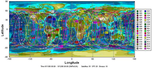
A network of artificial Earth satellites (AES) is deployed in near-Earth space, uniformly “covering” the entire Earth’s surface (Fig. 1). AES orbits are calculated with very high accuracy, so the coordinates of each satellite are known at any given time. The satellites’ radio transmitters continuously emit signals in the direction of the Earth. These signals are received by a GPS receiver located at a certain point on the Earth’s surface, the coordinates of which need to be determined.
The receiver measures the propagation time of the signal from the satellite and calculates the “satellite-receiver” range (the radio signal, as is known, propagates at the speed of light). Since three coordinates (plane coordinates X, Y and height H) must be known to determine the location of a point, the receiver must measure the distances to three different satellites (Fig. 2). Obviously, with this method of radio navigation (it is called non-request), the exact determination of the propagation time of the signal is possible only if the time scales of the satellite and receiver are synchronized.
Therefore, the satellite and receiver equipment includes reference clocks (frequency standards), and the accuracy of the satellite time standard is exceptionally high (long-term relative frequency stability is ensured at a level of 10-13 — 10-15 per day). Onboard clocks of all satellites are synchronized and tied to the so-called “system time”. The GPS receiver time standard is less accurate in order not to increase its cost excessively. This standard should only ensure short-term frequency stability — during the measurement procedure.
GPS Satellite Orbits
In practice, there is always an error in time measurements due to the mismatch between the time scales of the satellite and the receiver. For this reason, the receiver calculates a distorted value of the distance to the satellite, or “pseudorange”. The distances to all satellites with which the receiver is currently working are measured simultaneously. Consequently, the time discrepancy can be considered constant for all measurements. From a mathematical point of view, this is equivalent to the fact that not only the coordinates X, Y and H are unknown, but also the receiver clock correction D t. To determine them, it is necessary to measure pseudoranges not to three, but to four satellites. As a result of processing these measurements, the receiver calculates the coordinates (X, Y and H) and the exact time. If the receiver is installed on a moving object and measures Doppler frequency shifts of radio signals in addition to pseudoranges, the speed of the object can also be calculated. Thus, to perform the necessary navigation determinations, it is necessary to ensure constant visibility of at least four satellites from it. After the full deployment of the satellite constellation, 5 to 12 satellites can be visible at any point on Earth at any given time. Modern GPS receivers have 5 to 12 channels, i.e. they can simultaneously receive signals from this number of satellites. Redundant measurements (in excess of four) allow for increased accuracy in determining coordinates and ensure the continuity of the navigation task.
The system includes:
- satellite constellation (space segment);
- network of ground tracking and control stations (control segment);
- the GPS receivers themselves (consumer equipment).
Space segment
It consists of 26 satellites (21 main and 5 spare), which revolve in 6 orbits (Fig. 1). The orbital planes are inclined at an angle of about 55° to the equatorial plane and shifted from each other by 60° in longitude. The orbital radii are about 26 thousand km, and the orbital period is half a stellar day (approximately 11 hours 58 minutes). Each satellite has 4 frequency standards on board (two cesium and two rubidium — for backup purposes), solar batteries, orbit correction engines, receiving and transmitting equipment, and a computer.
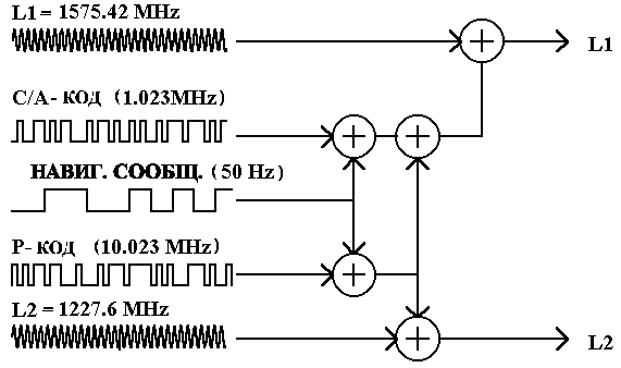
The satellite's transmitting equipment emits sinusoidal signals at two carrier frequencies: L1=1575.42 MHz and L2=1227.6 MHz. Before this, the signals are modulated by so-called pseudo-random digital sequences (more precisely, this procedure is called phase manipulation). Moreover, the L1 frequency is modulated by two types of codes: the C/A code (free access code) and the P code (authorized access code), and the L2 frequency is modulated only by the P code. In addition, both carrier frequencies are additionally encoded by a navigation message, which contains data on the satellite orbits, information on atmospheric parameters, and system time corrections (Fig. 3).
Coding of the radio signal emitted by the satellite has several purposes:
- ensuring the possibility of synchronizing the signals of the satellite and the receiver;
- creating the best conditions for distinguishing the signal in the receiver equipment against the background of noise (it has been proven that pseudo-random codes have such properties);
- implementing a limited access mode to GPS, when high-precision measurements are possible only with authorized use of the system.

The free access code C/A (Coarse Acquisition) has a pulse repetition rate (otherwise called “chips”) of 1.023 MHz and a repetition period of 0.001 sec, so its decoding in the receiver is quite simple. However, the accuracy of autonomous distance measurements using it is low.
The protected P code (Protected) is characterized by a pulse repetition rate of 10.23 MHz and a repetition period of 7 days. In addition, this code is changed once a week on all satellites. Therefore, until recently, only users who had received permission from the US Department of Defense could perform measurements using the P code. However, this “secret” became “obvious” as a result of a leak of classified information, after which a wide range of specialists gained access to the P code. The US Department of Defense took measures to additionally protect the P code: the AS (Anti Spoofing) mode can be turned on at any time without warning. In this case, additional encoding of the P code is performed, and it turns into a Y code. Decryption of the Y code is possible only by hardware, using a special microcircuit (cryptographic key), which is installed in the GPS receiver.
In addition, to reduce the accuracy of coordinate determination by unauthorized users, the so-called “selective access mode” SA (Selective Availability) is provided. When this mode is enabled, false information about corrections to the system time and satellite orbits is intentionally introduced into the navigation message, which leads to a decrease in the accuracy of navigation determinations by about 3 times.
Since the P-code is transmitted on two frequencies (L1 and L2), and the C/A-code — on one (L1), in GPS receivers operating on the P-code, the signal delay error in the ionosphere, which depends on the signal frequency, is partially compensated. The accuracy of autonomous distance determination by the P-code is approximately an order of magnitude higher than by the C/A-code.
Control segment
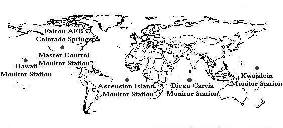
It contains the main control station (Falcon Air Force Base, Colorado), five tracking stations located at U.S. military bases in Hawaii, Ascension, Diego Garcia, Kwajalein, and Colorado Springs, and three staging stations: Ascension, Diego Garcia, Kwajalein (Fig. 5). In addition, there is a network of government and private satellite tracking stations that conduct observations to refine atmospheric parameters and satellite trajectories.

Ground stations for tracking satellites
The collected information is processed in supercomputers and periodically transmitted to the satellites to adjust orbits and update the navigation message.
Consumer equipment
In the consumer equipment (GPS receiver), the received signal is decoded, i.e. the code sequences C/A or C/A and P, as well as service information, are extracted from it. The received code is compared with a similar code generated by the GPS receiver itself, which allows determining the propagation delay of the signal from the satellite and thus calculating the pseudo-range. After capturing the satellite signal, the receiver equipment is switched to the tracking mode, i.e. the BPS maintains synchronism between the received and reference signals. The synchronization procedure can be performed:
- by C/A code (single-frequency code receiver),
- by P code (dual-frequency code receiver),
- by C/A code and carrier signal phase (single-frequency phase receiver),
- by P code and carrier signal phase (dual-frequency phase receiver).
The method of signal synchronization used in the GPS receiver is perhaps its most important characteristic.
Observation methods
The complex structure of the signal transmitted from the satellite to the receiver has determined the variety of methods for its processing and observation.
Code observations are implemented in the simplest GPS receivers. From the signal of frequency L1 received from the satellite, the C/A code is extracted (the receiver is then called single-frequency) or from the frequency signals L1 and L2, the P code is extracted (dual-frequency receiver). The corresponding code is compared with the reference code generated by the receiver itself. The accuracy of determining the coordinates is:
- for a single-frequency (L1) receiver — 100 m;
- for dual-frequency (L1, L2) receiver — 16m.
The accuracy values are given for an unfavorable measurement mode, when the “limited access” SA mode is enabled.
Phase observations are performed to improve the measurement accuracy. In this case, when comparing the signal received from the satellite and its standard generated in the receiver, not only the code but also the carrier frequency phase (L1 or L2) is taken into account. Since the carrier frequency period is hundreds (for the P code) and thousands (for the C/A code) times smaller than the periods of the code sequences, the accuracy of the comparison procedure is significantly increased, and, consequently, the accuracy of coordinate measurements increases. However, in this case, a problem of integer phase ambiguity arises, since there is no information on the number of integer periods of the information signal that fit on the path of the satellite — receiver. Only the fractional part of the signal phase delay (within one period) can be directly measured. Several methods are used to solve this problem:
- the classical two-stage measurement method, which involves performing a large number of redundant measurements at the first stage, and statistical analysis of the obtained data and determination of the most probable value of the phase ambiguity at the second stage;
- a modification of the classical method, which differs in that when processing the measurement results, multi-stage Kalman filtering is performed and a group of Kalman filters with optimal properties is selected;
- the antenna replacement method, when observations are made by two different receivers at two points in two different epochs. During measurements in the second epoch, the receiver antennas are replaced;
- the method of determining ambiguity “on the way”, when linear combinations of L1 and L2 signals (sums and differences) are used to determine the integer number of periods.
Sources of errors
The accuracy of coordinate determination is significantly affected by errors that occur during the measurement procedure. The nature of these errors is different.
- Inaccurate determination of time. Despite the accuracy of the satellite time standards, there is some error in the time scale of the satellite equipment. It leads to a systematic error in determining coordinates of about 0.6 m.
- Orbit calculation errors. Occurs due to inaccuracies in the forecast and calculation of satellite ephemeris performed in the receiver equipment. This error is also systematic and leads to a coordinate measurement error of about 0.6 m.
- Receiver instrumental error. Caused primarily by the presence of noise in the receiver's electronic path. The signal-to-noise ratio of the receiver determines the accuracy of the comparison procedure between the signals received from the satellite and the reference signal, i.e. the error in calculating the pseudorange. The presence of this error leads to a coordinate error of about 1.2 m.
- Multipath signal propagation. Occurs as a result of secondary reflections of the satellite signal from large obstacles located in the immediate vicinity of the receiver. In this case, the phenomenon of interference occurs, and the measured distance turns out to be greater than the actual one. It is quite difficult to estimate this error analytically, and the best way to combat it is considered to be rational placement of the receiver antenna relative to obstacles. As a result of this factor, the error in determining the pseudorange can increase by 2.0 m.
- Ionospheric signal delays. The ionosphere is an ionized atmospheric layer in the altitude range of 50 — 500 km, which contains free electrons. The presence of these electrons causes a delay in the propagation of the satellite signal, which is directly proportional to the electron concentration and inversely proportional to the square of the radio signal frequency. To compensate for the resulting error in determining the pseudorange, a method of dual-frequency measurements at frequencies L1 and L2 (in dual-frequency receivers) is used. Linear combinations of dual-frequency measurements do not contain first-order ionospheric errors. In addition, a correction model can be used to partially compensate for this error, which is analytically calculated using information contained in the navigation message. In this case, the value of the residual non-modeled ionospheric delay can cause an error in determining the pseudorange of about 10 m.
- Tropospheric signal delays. The troposphere is the lowest atmospheric layer from the earth's surface (up to a height of 8–13 km). It also causes a delay in the propagation of a radio signal from a satellite. The delay depends on meteorological parameters (pressure, temperature, humidity), as well as on the satellite's altitude above the horizon. Tropospheric delays are compensated for by calculating a mathematical model of this atmospheric layer. The coefficients required for this are contained in the navigation message. Tropospheric delays cause pseudorange measurement errors of 1 m.
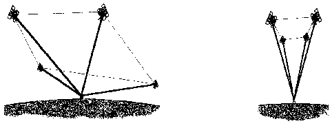
- Geometrical arrangement of satellites. When calculating the total error, it is also necessary to take into account the relative position of the consumer and the satellites of the working constellation. For this purpose, a special coefficient of geometrical deterioration of accuracy PDOP (Position Dilution Of Precision) is introduced, by which it is necessary to multiply all the errors listed above in order to obtain the resulting error. The value of the PDOP coefficient depends on the relative position of the satellites and the receiver. It is inversely proportional to the volume of the figure that will be formed if unit vectors are drawn from the receiver to the satellites. A large PDOP value indicates an unsuccessful arrangement of the satellite and a large error value. Fig. 5 shows examples of successful (a) and unsuccessful (b) geometrical position of the satellites. A typical average PDOP value fluctuates between 4 and 6.
Differential GPS mode
The most effective means of eliminating errors is the differential observation method — DGPS (Differential GPS). Its essence consists of performing measurements by two receivers: one is installed at the point to be determined, and the other — at the point with known coordinates — of the base (control) station.

|
a) |
- Главная
- Меню
- Войти / ЗарегистрироватьсяМоя учётная запись Учётная запись

Добавить комментарий