| The Key to High-Reliability Fire Alarm Systems
The Key to High-Reliability Fire Alarm Systems Ensuring high quality and reliability of fire alarm systems is the main task facing installers and designers of systems, as well as developers and manufacturers of components of such systems. In the field of fire automation and fire extinguishing, this task is given even more attention, since it is associated not only with the competitiveness of products in terms of their technical safety of people. Failures of system components, false alarms of detectors and devices can lead not only to material losses, but also to circumstances dangerous to the health and life of citizens.
The problem of quality and reliability assurance is complex and should be solved at all stages of the product life cycle. The key point in this direction is to ensure the efficiency of interaction between fire detectors and the fire control panel (FCP), since the reliability of fire alarm systems is largely determined by the physical principles of obtaining reliable information about the state of detectors in the fire alarm loop. The interface of communication between detectors and the FCP is established, as is known, by the device. Therefore, the quality of the entire fire alarm system depends on the choice of the device, with its features for connecting detectors: the ability to recognize true signals generated in the fire alarm loop, filtering distorted values of monitored parameters, proper processing of these signals and converting them into signals reproduced on the FCP panels, as well as into signals that are transmitted to external circuits, i.e. to alarms and to devices for transmitting notifications about a fire alarm or a malfunction.
If we analyze existing fire alarm control panels by the method of monitoring the fire alarm loop states, then the three most common methods are: The first two methods are used in fire alarm control panels to determine the state of dual-mode detectors, and the third is used for multi-mode addressable and addressable-analog detectors. The subject of the article is the analysis of the first two methods.
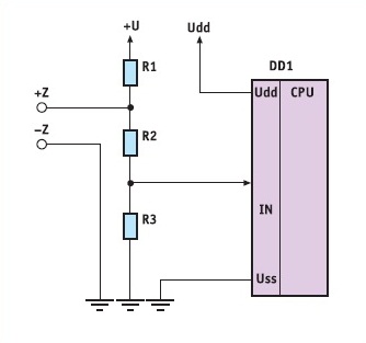
Many fire alarm devices [1, 2, 3] use the constant-current method of analyzing detectors according to the diagram shown in Figure 1.
Voltage Uz is supplied to the alarm loop via resistor R1, which limits the short-circuit current in this loop. The loop state is monitored by voltage drop using a voltage divider on resistors R2 and R3. This voltage divider matches the high supply voltage of the loop Uz with the permissible range of voltage values at the analog input of the microcontroller DD1. It is impossible to carry out automatic verification of a separate fire alarm loop on such devices, i.e. disconnecting the loop from the supply voltage for some time (3*6 s), during which the detectors must return to the standby mode if one of them for some reason goes into the fire alarm state. The resistance of resistor R1 equal to 1 kOhm, and this value (or close to it) is used in many fire alarm control panels, significantly limits the voltage in the fire alarm loop, and accordingly, the number of detectors that can function normally in such a loop, especially to ensure the strategy «Fire when two detectors are triggered in one loop». Another, more significant, disadvantage of such devices is the loop state control by voltage, which is ensured with a large total resistance (30 * 50 kOhm) of the voltage divider on resistors R2 and R3. Since the interference voltage that occurs in the loop can be many times greater than 24 V, then the interference voltage, exceeding the level of the useful signal, will be supplied to the analog input of the microcontroller along with the useful signal.
The values of voltage and current for such a device are given in Table 1, taking into account the possible resistance of the loop conductors up to 220 Ohm.
Table 1 shows that in the «Fire 2» mode, the voltage on the loop may be insufficient to keep the detectors in the triggered state. In addition, the current increases themselves for obtaining the «Fire 1» and «Fire 2» modes are insignificant. Some manufacturers of fire alarm control panels, for example, British ones [4], try to correct the shortcomings of such an organization of the fire alarm loop by reducing the value of resistance R1 by almost an order of magnitude from the resistance values of this resistor in domestic devices. As a result, the fire alarm control panel uses significantly more energy in the fire alarm state and it is necessary to reduce the voltage drop on the loop conductors by an order of magnitude. For such devices, it is also necessary to use detectors capable of switching current up to 100 mA. But one of the main shortcomings of such a scheme cannot be corrected — it is impossible to significantly increase noise immunity without changing the very principle of organizing the fire alarm loop. The sufficiently high impedance of the voltage divider on resistors R2 and R3 also does not contribute to noise immunity.
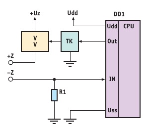
A more advanced circuit is shown in Figure 2. In this technical solution, instead of a resistor between the Uz and +Z circuits, a controlled current stabilizer E1 is used, which is switched off by the DD1 microcontroller through the E2 transistor switch. Voltage is supplied to the analog input of the DD1 microcontroller from the R1 resistor (Fig. 2), which is connected between the common bus and the «*Z» output of the fire alarm loop. Such coordination of signals arising in the fire alarm loop with the DD1 microcontroller may seem optimal in terms of the number of elements used, but it cannot be called optimal in terms of noise immunity. By using the controlled current stabilizer E1 in such a circuit, it becomes possible to limit the short-circuit current in the loop at the level of 20*30 mA, as well as to carry out automatic or semi-automatic verification. But to ensure the coordination of signals between the current in the loop and the voltage supplied to the analog input of the microcontroller DD1, the resistance of the resistor R1 should be 200*300 Ohm. Therefore, the in-phase component of the interference voltage will reach significant values on this resistor.
Thus, the disadvantage of such a fire alarm control panel is low noise immunity, which is due to the fact that it contains a resistor R1 for monitoring the current in the loops of the corresponding zones, the voltage drop on which reduces the stability of the voltage between the terminals «+Z» and «-Z» for connecting the zones from which the detectors are powered. In addition, this resistor reproduces the EMF of common-mode electrical interference relative to the common bus of the fire alarm control panel, which is usually grounded.
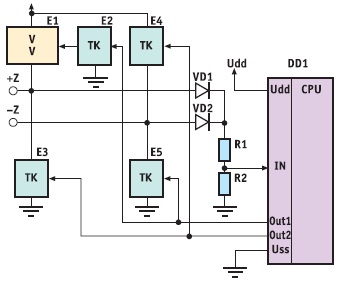
The use of loops with alternating voltage formation in fire alarm control panels does not improve the noise immunity of fire alarm systems [5]. An analysis of technical solutions used in such fire alarm control panels can be carried out on the basis of the block diagram shown in Figure 3.
The significant differences of this technical solution from the previous circuits are the use of negative polarity pulses in the fire alarm loop. They are generated from an additional negative voltage power source –Uz by an additional transistor switch E3, which is controlled from the same pin of the DD1 microcontroller as the first transistor switch E2. Current control in the loop is carried out on the resistor R1 similar to the previous circuit shown in Figure 2. Voltage converter E4 ensures the matching of negative voltages that appear on the resistor R1 with the range of possible voltages on the analog inputs of the DD1 microcontroller.
Due to the fivefold excess of the value of +Uz = 24 V over the voltage on the resistor R1 (maximum value = 4.75 V), sufficient voltage is provided between the terminals «+Z» and «-Z» to power the detectors. However, even in this matching circuit, the resistance value of the resistor R1 remains quite large, which contributes to the allocation of a common-mode component of the interference voltage on it. The absence of a load resistance at the end of the loop somewhat reduces the total current consumption of such a fire alarm control panel, but creates additional conditions for false alarms, especially at the end of the loops, due to the inductance of the conductors. In direct-current loops, the current through the end resistor reduces the quality factor of the inductances of these conductors, which in turn reduces the likelihood of false alarms. In addition to susceptibility to external interference, the loop itself becomes a source of electromagnetic interference. This is due to the fact that in the alternating fire alarm loop based on the PPCP, the block diagram of which corresponds to Figure 3, the change in voltage polarity occurs very quickly, therefore the fronts of electrical pulses in the loops create electromagnetic pulses at the places where the detectors are connected, which complicate the operation of fire detectors, especially smoke detectors. It should also be noted that the duration of negative polarity pulses in almost all PPCPs with alternating voltage does not exceed 20 ms, therefore it can be confidently stated that such devices do not use the method of integrating signals over a time multiple of 20 ms.
Other technical solutions used in the FPCP with alternating voltage (Fig. 4) provide switching of the loop by a bridge switch, which is powered from one power source +Uz and controlled by two outputs Out1 and Out2 of the DD1 microcontroller. Due to the fact that in the bridge switch the transistor keys E2 and E5, as well as E3 and E4, are switched in pairs with the corresponding delay of one pair relative to the other, there are no through currents through the current stabilizer E1 and the transistor key E3, as well as through the transistor keys E4 and E5. At the same time, smooth fronts of switching the polarity of the voltage make it impossible for false alarms to be triggered by the pulse power supply of such a loop.
But this circuit still has fundamental disadvantages, such as high impedance and inductance of the loop, as well as control of the state by the voltage drop on the loop using a high-resistance voltage divider on resistors R1 and R2.
In addition, there are other problems in devices with alternating voltage of fire alarm loops that complicate the processing of information about the state of the loop with active fire detectors. Developers of such devices should take into account that active fire detectors cannot be identified with passive contact detectors. The features of active detectors are clearly visible when several dozen such detectors are connected to a loop with alternating voltage. It is unacceptable to evaluate the state of such loops several microseconds after the change in the sign of the voltage supplying the loop.
There is also a whole class of devices to which only four-wire fire detectors can be connected. For example, when the voltage in the loop of such a device in standby mode does not exceed 5*8 V, which is insufficient for the normal operation of many fire detectors. To match two-wire detectors with such devices, loop matching modules of the MUSh series [6] are used. Practical testing of these transformations by many installers confirmed the effectiveness of the provided technical solutions.
In order to ensure the construction of a truly protected fire alarm loop, which is capable of reducing the noise level by at least 70 dB [7], it is necessary to use fundamentally different schemes for constructing the fire alarm control panel. It is precisely these schemes that were used in devices built on the basis of innovative solutions proposed by a team of engineers and inventors [8, 9].
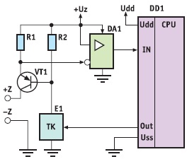
Figure 5 shows the block diagram of the first device implemented by the above co-authors. The features of this solution are that the “–Z” pin is grounded, and the VT1 transistor acts as a switch and current limiter. This transistor is controlled by the DD1 microcontroller through the E1 transistor switch. The current in the loop is monitored by the voltage drop across the R1 resistor. The resistance of this resistor is small – about 100 Ohm, and the required gain is provided by the DA1 differential amplifier.
By using this circuit, it is possible to control the current in the fire alarm loop with a slight voltage drop on the measuring resistor R1. There is practically no common-mode component of the interference voltage, because the “–Z” terminal is grounded. With a stabilized voltage of +Uz, the voltage at the output of the differential amplifier will be proportional to the current flowing in the loop circuit. A significant limitation of the voltage on the loop is noticeable at currents greater than 20 mA. And the current in the loop, which the device evaluates as an open circuit, does not exceed 3 mA. Therefore, the current through the end-of-line resistor should exceed this value and be, for example, 3.5 mA. To ensure the “Fire on two active detectors” strategy, an additional resistor to the active detector with an internal resistance of 0.5 kOhm should provide a current increase from the operation of the first detector not
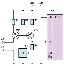
The disadvantages of this solution include a complex signal matching circuit on the differential amplifier DA1, but in a multi-loop device, only one amplifier can be used, sequentially monitoring the voltage on the resistor R1 of each loop with a multiplexer. This disadvantage can be corrected by the technical solution according to the second patent, which is shown in Figure 6.
The matching of signals between the voltage at the input of the microcontroller DD1 and the current in the loop is performed on the basis of a transistor current mirror with the required conversion coefficient. The transistor key E1 matches the signal levels for controlling the state of transistors VT1 and VT2 from the microcontroller DD1. Since the voltage drop across the resistor R2 is the base for two transistors, the resistance of the resistor R1 will set the short-circuit current in the loop, and the collector current of the second transistor VT2 can be an order of magnitude less than the collector current of the first transistor VT1.
Another feature of this technical solution is that the operating modes are practically independent of the choice of voltage on the cable, be it 15 or 24 V.
Each fire alarm control panel has its own advantages and disadvantages. The two patents presented, of course, do not solve all the problems associated with the reliable operation of fire alarm systems. But to eliminate the shortcomings, extraordinary technical solutions are simply necessary, in other words, inventions that should form the basis of an innovative model for solving problems. At present, clear interaction between organizations developing fire alarm control panels and organizations developing fire detectors is extremely important. The correct approach to understanding the features of each component of the system, with proper coordination of fire alarm control panels and high-reliability detectors. V. Bakanov, Chief Designer of Arton Private Enterprise LITERATURE:
«Algorithm of security» magazine №6, 2010 |


