Television spectral systems for forensic examinations.
V. V. Butusov, N. P. Kornyshev, Ph.D., Associate Professor, O. F. Rodionov, V. I. Chelpanov
Currently, television spectral systems (TSS) are beginning to be widely used for forensic examinations of documents.
The TSS is understood to be a combined television equipment, with the help of which the following studies are carried out according to standard forensic methods:
- detection of various types of document forgeries: identification of traces of etching, mechanical erasure, additions, corrections in the original text, as well as identification of the sequence of execution of the text, signatures and application of seals and stamps (by intersecting strokes);
- establishing the method of applying seal and stamp impressions: flat, relief, intaglio printing form, determining the differences between the standard seal impression and the seal impression on the document;
- establishing the method of producing document forms (flat (offset), relief, intaglio printing);
- detecting the presence of special marks, stamps, microfonts and other security elements on documents and securities;
- detecting low-contrast, weakly luminescent traces on documents;
- detection of filled-in, crossed-out or faded (extinct) texts, records formed by indented strokes or made on carbon paper, etc.;
- detection of the structure of the document material;
- detection of the structure of the fabric;
- detection of contamination on fabrics (soot and mineral oil residues) in case of gunshot wounds and transport accidents;
- detection of washed-out traces of blood, as well as traces of blood located on motley, dark and dirty objects.
TCS allows conducting research in the following modes:
- in reflected UV rays, visible rays and IR rays;
- in transmitted visible or IR rays;
- luminescent analysis in the visible spectrum region under the influence of UV rays;
- luminescent analysis in the IR spectrum region under the influence of visible rays;
- in oblique light;
- spectrozonal analysis.
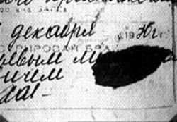
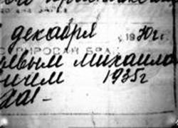
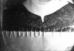
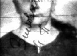
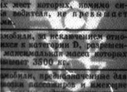
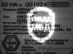
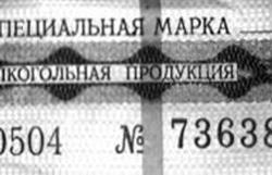
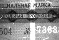
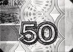
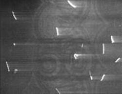
Below in Fig. 1 are some images of document fragments obtained using television spectral systems.
 |
|
|
Fragment of the passport in reflected visible (left) and IR (right) light |
|
 |
 |
|
Fragment of the passport in visible oblique (left) and in transmitted IR (right) light |
|
 |
 |
|
Driver's license (ultraviolet luminescence) |
|
 |
 |
|
Excise stamp in reflected visible light (left) and ultraviolet luminescence of the stamp number and security strip (right) |
|
 |
 |
|
Bank note in reflected visible light (left) and infrared luminescence of protective fibers (right) |
|
Fig. 1. Examples of images of document fragments obtained using TSS.
Currently, three model series of TSS can be conditionally distinguished, differing from each other in their purpose and, accordingly, in the level of complexity.
The first model series should include TSS for express analysis of documents at checkpoints such as “DVC Portable (Switzerland), “Regula 4004M” (Belarus), TSS-3M (Russia).
The second model series of TSS, intended for conducting document research in forensic departments at district and city levels, includes systems of the type “VSC-4 (Great Britain), “VSK-1”, “Expert” (Russia).
The third model series of TSSs intended for in-depth examination of documents in forensic departments at regional and national levels should include systems of the “VSC-1”, “VSC-2000 (United Kingdom), “Docubox”, “Docuzenter” (Germany), ED-1100” (Belarus) type, as well as the Russian “Expert-K”, “Raduga” systems.
Most TSSs are available in black and white or color. The advantage of the black and white version is its high sensitivity.
In addition to the capabilities of black-and-white systems, color television spectral systems provide observation of color images of objects examined in the visible spectrum under direct and oblique illumination, as well as under luminescence under the influence of ultraviolet rays.
This allows for a comparative analysis of the objects under study by color differences with reference samples and significantly increases the efficiency of detecting counterfeit documents and securities that have color security elements, such as Orlov and iris printing, background mesh, colored luminescent fibers or images, etc.
Let us consider the design features of the TSS for each of the listed model series using the example of the domestic systems TSS-3M, «Expert» and «Raduga».
Television spectral system TSS-3M
This system is designed for express analysis of documents directly at traffic police checkpoints, customs, various security services, etc.
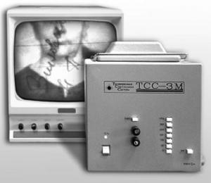
Fig. 2. External appearance of the TSS-3M television spectral system.
Features of the system:
- efficiency, simplicity and convenience of express analysis of documents;
- correction of the video signal for effective detection of luminescence
- the ability to measure the linear and angular dimensions of seals and stamps using removable glasses with measuring grids.
System composition:
- analyzer
- black and white (color) monitor with a screen diagonal of 9 or 12?
|
Operating mode |
Light source |
Wavelength range |
Bandwidth of built-in light filters |
|
|
Incident light |
ultraviolet |
2 UV lamps of 4W |
l = 365 nm |
300-400 nm |
| visible |
2 halogen lamps 20 W each |
400-600 nm |
||
| infrared |
4 IR LEDs 15 mW each |
l = 870 nm |
||
| Oblique light | visible |
4 incandescent lamps 0.5 W each |
l = 400-1000 nm |
400-600 nm |
| Transmitted light | Infrared |
4 IR LEDs of 15 mW each |
l = 870 nm |
|
Technical specifications:
Spectral sensitivity 365-1000 nm
Resolution 375 tel. lines
Size of the controlled field 32×42 mm
Size of the controlled document 297×210 mm
Supply voltage 220 V
Overall dimensions:
— analyzer 231x248x260 mm
— monitor 233x225x213 mm
Weight:
— analyzer 7 kg
— monitor 5 kg
Functional diagram and design features of the TSS-3M analyzer
The functional diagram of the TSS-3M analyzer is shown in Fig. 3.
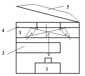
Fig. 3. Functional diagram of the TSS-3M analyzer
1. Photodetector;
2. Mode selection unit with C2 light filter input unit;
3. Combined IVL with C1 light filters;
4. Object plane with a transparent window;
5. Folding clamp with a built-in transmitted light source.
A feature of the TSS-3M [N. P. Kornyshev, O. F. Rodionov, “Television system for document control”, patent No. 2094849, no. and. 30, 1997, N. P. Kornyshev, O. F. Rodionov, N. G. Troshin,
The television spectral system”, patent 2066930, no. 26, 1996] is a design that ensures maximum simplicity, high efficiency and convenience of express analysis of documents.
The document under examination is mounted on the object plane – 4 with a transparent window and pressed with a folding clamp with a built-in source – 5 of transmitted light, which simultaneously protects the document under examination from extraneous light. The TSS-3M provides fixed focusing in the object plane.
The document under examination is illuminated through a transparent window with ultraviolet, visible or infrared light, switched on in the combined luminescence excitation source (LEVL) – 3 depending on the selected operating mode by block – 2. Block 2 ensures, simultaneously with switching on the light source with absorption spectrum C1, the input of light filter C2 in front of photodetector –1, which isolates the luminescence spectrum.
The combined IVL TSS-3M has a UV light source with a UFS-5 light filter and a blue-green light source with a SZS-21 light filter.
The set of C2 light filters in the TSS consists of two light filters: type ZhS11 for isolating luminescence in the visible spectrum under the influence of ultraviolet light and KS-19 for isolating infrared luminescence under the influence of blue-green light.
Expert television spectral system
This system is designed to conduct document research in forensic laboratories.
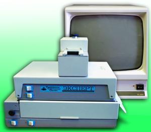
Fig. 4. Television spectral system «Expert»
Features of the system:
- the presence of a light-protective box, which enables work with three-dimensional and extended objects;
- fragment-by-fragment study of large-sized objects by installing the analyzer directly on the object being studied;
- increased field of view (60×90 mm) and discrete 4-fold change in image scale by quickly changing lenses;
- video signal correction for effective detection of luminescent traces on documents in the visible and IR spectral regions;
- the presence of 20 light filters in the form of 2 lines, highlighting individual sections of the spectrum in the range from 400 to 1000 nm, for conducting spectrozonal studies of objects.
System composition:
- analyzer;
- power supply;
- light source with light-protective box;
- black-and-white (color) monitor 9″, (12”).
|
Operating mode |
Light source |
Light source wavelength range |
Built-in light filters bandwidth |
|
|
Incident light |
ultraviolet |
2 UV lamps 4 W each |
l = 365 nm |
300-400 nm |
| visible |
2 x 20 W halogen lamps |
l = 400-1000 nm |
400-600 nm |
|
| wide spectrum visible and infrared range) |
8 incandescent lamps 0.5 W each |
l = 400-1000 nm |
||
| infrared |
4 IR LEDs 15 mW each |
l = 870 nm |
||
| Oblique light | wide spectrum (visible and IR range) |
2 halogen lamps of 20 W |
l = 400-1000 nm |
|
| Transmitted light | wide spectrum (visible and IR range) |
2 halogen lamps of 20 W |
l = 400-1000 nm |
|
Technical specifications:
Spectral range 365-1000 nm
Resolution 375 tel. lines
Size of the studied field of view 60×90, 15 x 22 mm
Supply voltage 220 V
Overall dimensions:
— analyzer 306x234x256 mm
— power supply 50x135x74 mm
— light source 325x240x88 mm
— monitor 223x225x13 mm
Weight:
— analyzer 5.0 kg
— power supply 1.5 kg
— light source 2.6 kg
— monitor 5.0 kg
Functional diagram and design features of the TSS Expert analyzer
The functional diagram of the TSS Expert analyzer is shown in Fig. 5.
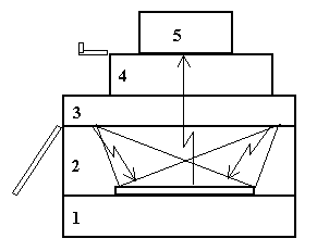
Fig. 5. Functional diagram of the TSS “Expert”
- Source of transmitted light;
- Light-protective box with hinged doors;
- Combined artificial light with C1 light filters;
- Optical attachment with an input unit for a line of C2 light filters;
- Photodetector.
The design feature of the TSS Expert is the presence of a small-sized light-protective box — 2 with hinged doors, inside which the object under study is located on the object plane of the transmitted light source — 1.
The combined IVL — 3 is similar to the TSS-3M IVL. The optical attachment — 4 provides the ability to discrete 4-fold scaling by changing lenses, as well as focusing the image of the object under study, the need for which may arise when it is placed in a light-protective box.
The filter input unit allows the input of a standard set of color glass filters into the rear working segment of the lenses.
Unframed black-and-white or color television cameras with increased sensitivity from the EVS company are used as photoreceivers.
The TSS “Expert” allows for more detailed spectrozonal studies compared to the TSS-3M due to its increased set of C2 light filters that highlight the luminescence spectrum.
Rainbow-2 Television Spectral System
This system is designed to conduct in-depth forensic studies of documents and other material evidence in forensic laboratories and centers. The appearance of the system is shown in Fig. 6.
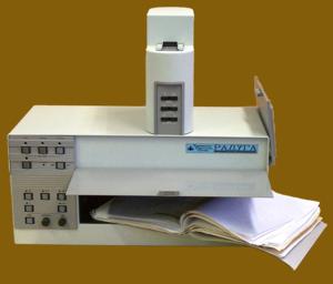
Fig. 6. Television spectral system «Raduga-2»
System capabilities:
- Image input into the computer and its additional processing;
- High-power pulsed light sources;
- Smooth change of image scale (6, 10, 16-fold varifocal lens);
- Significantly increased field of view.
System features:
- high intensity of UV illumination ensures effective detection of luminescent objects (fragments) in the UV mode;
- the presence of high-power pulsed light sources in the visible and UV ranges ensures detection of weakly luminescent objects (fragments) in the PCL and UV mode;
- the ability to change the spectrum of the pulsed visible light source by replacing additional light filters from the accessory kit;
- the ability to accumulate (integrate) images when working with a computer in order to identify low-contrast fragments or elements of the object being examined;
- the large size and original design of the light-protective box allow you to examine three-dimensional objects and documents, stitched folders;
- large field of view (120×160 mm) and smooth 6, 10 and 16-fold change in image scale using a varifocal lens;
- the presence of 20 light filters in the form of lines, highlighting individual sections of the spectrum in the range from 400 to 1000 nm, for conducting spectrozonal studies of objects;
- inputting an image into a computer, its additional processing (including using standard graphic editors), creating an image archive;
- an additional light source on bright light-emitting diodes, providing illumination of the studied surface with a diameter of 20 mm.
System composition:
- analyzer;
- PCI Capture Card image input board;
- software.
|
Operating mode |
Light source |
Light source wavelength range |
Built-in light filters bandwidth |
|
|
Incident light |
ultraviolet |
2 x 15W UV lamps |
l = 365 nm |
240-400 nm |
| visible |
2 halogen lamps |
l = 400-1000 nm |
400-600 nm |
|
| wide spectrum (visible and IR range) |
2 halogen lamps |
l = 400-1000 nm |
||
| pulsed UV range |
pulse lamp |
300-400 nm |
||
| pulsed visible range |
pulsed lamp |
400-750 nm; 400-520 nm; 400-600 nm; 400-650 nm; 480-750 nm; 530-750 nm; 580-750 nm; 480-600 nm; 480-650 nm; 530-650 nm |
||
| Oblique light | wide spectrum (visible and IR range) |
2 halogen lamps of 20 W |
l = 400-1000 nm |
|
| Transmitted light | wide spectrum (visible and IR range) |
2 x 20W halogen lamps |
l = 400-1000 nm |
|
| Additional light source | Spectrum regions: blue, green, yellow, orange, red |
6 types light emitting diodes: |
l = 470 nm |
|
Technical specifications:
Spectral range 254-1000 nm
Resolution:
— black and white image option 500 tel. lines
— color image option 400 tel. lines
Number of light filters 20 pcs.
Size of the examined field of view during operation:
— with a 6x varifocal lens from 112×148 mm to 21×28 mm
— with a 10x varifocal lens from 105×140 mm to 12×16 mm
Supply voltage 220 V
Overall dimensions of the analyzer 550x260x410 mm
Weight of the analyzer 15 kg
Functional diagram and design features of the TSS “Raduga” analyzer
The functional diagram of the TSS Raduga” analyzer is shown in Fig. 7.
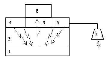
Fig. 7. Functional diagram of the TSS “Raduga”
- Source of transmitted light;
- Light-protective box with hinged walls;
- Combined artificial ventilation;
- Pulsed artificial ventilation of the visible range;
- Pulsed artificial ventilation of the UV range;
- BKT;
- Combined artificial lung ventilation with LEDs.
The design feature of the TSS Raduga” is the presence of an enlarged light-protective box, more powerful continuous UV-range IVL (2×15 W for 254 and 365 nm), as well as pulsed IVL for detecting weakly luminescent objects in the visible and infrared spectral regions. The TSS Raduga has an additional combined IVL on LEDs, with the help of which it is possible to illuminate an object in the light-protective box with light with a wavelength of 470, 567, 590, 615, 626 or 655 nm in a field with a diameter of about 30 mm.
Let's consider in more detail the TSS Raduga” BKT, which is shown in Fig. 8 .
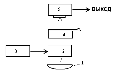
Fig. 8. Functional diagram of the BKT TSS “Raduga”
1. Corrective lens;
2. Vari-angle lens;
3. Vari-angle lens control unit;
4. Light filter input unit;
5. Photodetector.
The BKT uses a motorized vari-angle lens –2 from COMPUTAR with a zoom factor of 6.10 or 16x.
In front of the zoom lens, to ensure its operation in fields of view from 160×120 mm with a smooth increase in scale at a distance that allows minimizing light loss from the object under study, a correcting lens — 1 is installed. From block -3, the zoom, focusing and diaphragm of the zoom lens are controlled by supplying control voltages to its corresponding motors.
Using the light filter input unit 4, light filters C2 from a discrete set (line) of colored optical glasses are introduced into the rear working segment of the lens.
The design of the unit allows, if necessary, to replace the rulers and thereby change the spectral characteristic of the BKT. As a photodetector — 5 in the BKT, frameless television cameras of the EVS company with increased sensitivity of black-and-white or color images are used.
The color image camera is adapted to work in a wide range of the spectrum from the long-wave UV region (380 nm) to the near IR region of the spectrum (1000 nm).
For this, the bandpass filter in front of the color matrix is removed. Correct color rendering when working in the visible range of the spectrum is achieved by installing in the discrete set the appropriate light filter, identical to the removed bandpass filter.
The video signal from the BKT is fed through the correction unit (UKVS), which allows increasing the contrast of the resulting image due to additional fixation of the black level and amplification of the video signal, to the output of the TSS, connected to the image input device in the PC or to the video viewing device.
Features of the TSS operation in pulse mode
Let's turn to Fig. 9 with timing diagrams.
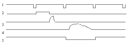
Fig. 9. Timing diagrams of the process of obtaining
an information television frame in the pulse mode of the TSS.
- Frame sync pulses (FSP);
- Flash trigger pulse;
- Flash;
- Information frame;
- Image recording signal into memory.
In the pulse mode of the TSS, it is necessary to ensure synchronization of the processes of the flash of the flash lamp and the recording of the single information television frame following the flash.
For this, with reference to the CSI (diagram 1), a trigger pulse is formed (diagram 2), which ensures the triggering of the flash lamp during the forward stroke of the frame scan (diagram 3) and the formation of a potential relief from the illuminated scene in the accumulation section of the CCD matrix.
The television frame following the flash is informational (diagram 4) and must be recorded in the memory device (diagram 5).
A single frame, especially when visualizing a low-contrast image, is very noisy. Noise suppression for a static subject can be accomplished by summing the signal in digital memory over several pulse exposure cycles with subsequent averaging over their number.
Despite some difficulties in achieving synchronization, the algorithm described above can be implemented by controlling the pulse lamp via the COM port of the PC and recording the image via a standard image input device that supports the OVERLAY hardware viewing mode.
In this case, the flash trigger pulse can be tied to the moments of image update in the PC video buffer and considered as some system frames, the duration of which depends on the parameters of the PC and the video recording device. To ensure that the flash moment reliably matches the direct frame scan of the television sensor, the trigger pulse must have an adjustable software delay.
In addition, to fix the information frame, it is necessary to ensure software selection of one of several system frames updated in the PC video buffer after the flash control signal is generated.
This control option has proven to be quite stable when working with TSS on PCs of various modifications, starting from Intel PII 300 MHz, however, it is necessary to select delay values individually for each system.
TV magnifying glass «VM-2 Video Mouse»
The TV magnifying glass is designed to examine document fragments with a magnification of 40-60x.
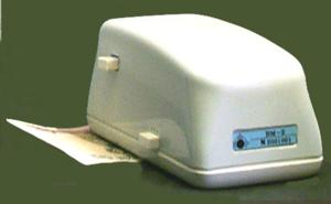
Fig. 10. TV magnifier «Video mouse VM-2»
The TV magnifier has the following operating modes:
- wide spectrum, created by mixing blue (470 nm), green (567 nm) and yellow (590 nm) colors;
- blue region of the spectrum (470 nm);
- green region of the spectrum (567 nm);
- yellow region of the spectrum (590 nm);
- red region of the spectrum (655 nm);
- IR region of the spectrum (810 nm);
- oblique light in the green region of the spectrum (567 nm);
- oblique light in the IR region of the spectrum (810 nm);
- IR luminescence.
Technical specifications:
Resolution 375 tel. lines
Size of the controlled field 3×4 mm
Supply voltage 12 V
Current consumption, no more than 250 mA
Overall dimensions 120x75x65 mm
Weight 0.5 kg
Connects directly:
- to a black-and-white TSS analyzer of any of the basic options;
- to a television microscope;
- to a video signal switch;
- or used autonomously in a set with a power supply and a monitor.
Functional diagram and design features of VM-2
The functional diagram of VM-2 is shown in Fig. 11.

Fig. 11. Functional diagram of VM-2
- Photodetector;
- Input unit of light filter C2;
- Combined light source on LEDs;
- The surface of the document under study.
A special feature of the VM-2 is its design [S. A. Arkhipov, A. N. Gerasimov, N. P. Kornyshev, “Reading Device”, patent No. 2134932, no. and. 23, 1999] in the form of a “mouse” manipulator, which allows for the examination of document fragments with minimum dimensions of 3×4 mm by moving them along the surface of the document, which corresponds to approximately a magnification of 45x when displayed on a monitor with a screen size of 9″. The VM-2 provides the ability to visualize IR luminescence when illuminating an object with blue LEDs and introducing a C2 type KS-19 light filter in front of the photodetector – 1 using the -2 unit.
Table of comparative characteristics of the TSS for in-depth examination of documents
Analyzing the technical parameters of television equipment available on the market for the study of the authenticity of documents and other material evidence, we can state the presence of a fairly wide range of TSS, which allows the consumer to successfully solve his problems.
The table of comparative characteristics provides the parameters of the best domestic and foreign analogues of equipment for in-depth study of documents.
At the same time, it is possible to note a sufficiently high technical level of TSS of Russian and Belarusian production, which allows these systems to successfully compete in the domestic market with similar imported equipment.
The main trends in the development of TSS are aimed at saturating the equipment with service functions, programmatically set from the PC. In particular, work in automatic mode according to a given algorithm for examining documents with fixation of images obtained in various modes, automated control of the positioning of light filters, scale and aperture in the BKT.
Another direction of development of the TSS is to increase their sensitivity, selectivity and resolution.
Increased sensitivity is associated with improved energy characteristics of the ILC and improved parameters of photodetectors: sensitivity and signal-to-noise ratio.
Increased selectivity is associated with the use of narrow-band interference filters, which allow for finer differentiation by spectrum in order to detect color differences in documents, as well as to highlight certain areas in the luminescence spectrum.
Increased resolution is associated with the use of full-format CCDs — matrices that ensure compliance with the television broadcasting standard.
To obtain images with higher resolution, in the near future we should expect the use in TSS of digital cameras adapted for operation in specific operating conditions of the system, in particular, in a spectral range extended in relation to the visible part.

Добавить комментарий