| Some features of choosing the position and orientation of television cameras
Some features of choosing the position and orientation of television cameras Numerous television reports on crime events with video recordings of vague silhouettes, from which it is practically impossible to obtain any significant information about the criminals, and graphic examples of improper installation of television cameras on the streets served as a reason for writing this article. What are the words from the report worth that the TV system «made it possible to compile a description of the criminal — of average height and strong build» — is this all that the most informative part of the security system could do at the present time?! And this happens despite the presence of a large number of publications in this area, for example, an excellent series of articles by A. Popov, works by Yu. Gedsberg and a number of other authors. Let us consider the features of some typical tasks of installing television cameras (TC), in which errors are often made that significantly reduce the real capabilities of the television surveillance system. Obviously, the choice of the position of television cameras in space significantly affects the functional characteristics of TV surveillance systems. First of all, such as the information content of the image, its quality and the size of the controlled area. This choice depends on a number of general factors, as well as on the specific features of the specific task of constructing a TV surveillance system. Moreover, these factors and features often impose conflicting requirements on the choice of location, installation height and orientation of the TV camera. Therefore, when choosing the above parameters, a compromise problem is usually solved. From this point of view, optimization of the choice of installation height and position of the TV camera allows achieving gains in a number of parameters at practically the same costs. For example, increasing the size of the monitored zone, increasing the information content of the image and/or improving its quality. FACTORS DETERMINING INSTALLATION HEIGHTLet's consider the main factors influencing the choice of the TV camera position. In general, the position of the TV camera in space is determined by such parameters as installation height, the location of the TC relative to the controlled viewing area and its orientation in space. Obviously, this issue cannot be considered without taking into account the features of choosing the viewing angle and the resolution of the system [1]. CAMERA PROTECTIONUsually, the task of security systems is to provide not only an overview of a certain area, but also control over the state of the TC itself. This is necessary to reduce the likelihood of unauthorized impact on the TV camera as an element of the security system. From the point of view of the security of the TV camera, the installation height should be chosen large enough to minimize the possibility of direct mechanical, as well as other types of impact on the TC. Let's consider what these impacts can be.
Fig. 1 Damage to the television camera by falling icicles In terms of eliminating the possibility of the unauthorized actions discussed, the height of the TC installation should be chosen as high as possible (within reasonable limits, of course). At least to eliminate direct impacts on the camera without using means of «extending» the arm — a stick and similar devices. If, of course, the design of the object allows it. However, the consequence of increasing the installation height at a fixed distance from the controlled area will be an increase in the angle of inclination, leading to a change in the angle. The latter can cause unacceptable distortions, for example, in identification or action recognition tasks. This feature will be discussed below. DESIGN FEATURES OF THE OBJECTOften, the design features of an object, on the one hand, allow solving some problems of camera protection, and on the other hand, create restrictions on the choice of their installation location. For example, the choice of installation location may be determined by the presence of a cornice on the building, under which a camera can be installed in order to avoid direct exposure to precipitation (rain and snow) or damage to the camera by snow or icicles falling from the roof. That is, to increase its protection. Figure 1 shows an example when failure to take into account the above-mentioned circumstance led to damage to the camera. At the same time, a slight shift to the left (under the balcony) would have easily avoided this. Another example — existing poles on the monitored territory, on which a camera can be installed, also to a certain extent limit the choice of its installation location. DIMENSIONS OF THE VIEWING AREAAll other things being equal, for example, with a constant viewing angle, the size of the monitored area will change depending on the installation height of the TV camera. Therefore, if it is necessary to increase the size of the monitored area as much as possible, this can be achieved by simply increasing the installation height. But at the same time, one should not forget about meeting the resolution requirements and the effect of changing the angle on the resulting image. Also, the determining factor can be the reduction of shadow zones with an increase in the installation height. Therefore, if, for example, only video monitoring of the presence of objects in the monitored area is required, and at the same time changing the angle does not significantly affect the problem being solved, then it is also possible to increase the installation height of the TC. It is clear that if the installation height is increased not for the purpose of increasing the viewing area, then it is necessary to correct the focal length of the lens towards an increase in its value to bring the size of the viewing area to the required one. IMAGE AREAS THAT CAN'T BE SEENWhen there are various objects or surveillance objects in the television control zone, image areas that cannot be seen appear. That is, so-called «dead zones». Such zones can be:
In all cases, it becomes possible to overcome at least part of the zone without being in the field of view of the TV camera. For example, knowing the location of the TV camera, you can move around the underground parking lot, «covering» yourself with the supports of exhausted cars. Therefore, it is necessary to take into account that not only existing blind zones can be used, but also artificially created ones. INFLUENCE OF THE ANGLE OF INCLINATIONWhen changing the angle of inclination, the ratio of the visible and real sizes of objects will change. That is, certain distortions of the object's image will appear. Strictly speaking, such changes will take place both with a fixed camera position and with a changing position of the object in the viewing area. That is, when changing the angular direction of the object under observation. But for the initial assessment, we will assume that the object is on the axis of the TV camera. Also, for simplicity, we will assume that the object is flat and located vertically. If the camera axis is perpendicular to the plane of observation, then the real image of a flat object and its visible image will coincide. When changing the height of the camera installation and the corresponding increase in the angle of inclination, the visible size of the object of observation in the horizontal plane changes relatively little or does not change with the corresponding adjustment of the focal length. But in the vertical plane it will depend on the angle of the camera. The latter, in turn, usually depends on the height of the installation. Figure 2 shows, for example, visible images of an object (shown in Figure 2, a) with a camera directed to the plane of the object at angles of 30° and 45° in Figures 2, b and 2, c, respectively. Obviously, there is a change in the ratio between the sizes of the visible image in the horizontal and vertical planes. The magnitude of such distortions can be characterized by the coefficient K(?) of linear distortions equal to the ratio of the visible DView and real DReal sizes. The difference will be determined by the value of the angle of the camera ? and will be equal to:
The graph characterizing the distribution of the image distortion value
as a function of the tilt angle ? is shown in Figure 3. It is evident that at angle values greater than 20°-25° the distortions increase quite rapidly, which must be taken into account when selecting the value H of the height of the television camera installation. Also, for objects located in the lower part of the viewing area, additional distortions will appear. Since an additional component of the tilt angle (or more precisely the angular direction to the observation object) appears. This is illustrated in Figure 4. Fig. 2Distortion of the visible image Fig. 3 Linear distortion Fig. 4 Changing the angular direction of the object Fig.5Formation of an image with a large angle of inclination of the TC Fig. 6 Television monitoring of the flow of people Fig. 7 Television monitoring of the flow of people with a higher installation height of the TC
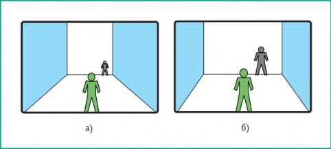
This component can reach a value equal to half the viewing angle?/2 in the vertical plane. That is, the total value of the angle will be ?+?/2. And vice versa, for objects in the far part of the viewing area, the distortion will be less. When it comes to solving the problem of action recognition, there are usually no particular difficulties. However, if it is necessary to solve the problem of identification, it may be difficult to solve or not solve at all. Especially if the person tilts his face down, which significantly worsens the situation. It is also necessary to clearly understand that real objects are not planar. Therefore, the actual distortions will be nonlinear and can be much larger. A real example of not taking into account the considered factor is shown in Figure 5 [2]. In this situation, a «top view» of the subject of observation is formed. Obviously, no significant information about him can be obtained from such an image. TELEVISION CONTROL OF THE STREAM OF PEOPLEOne of the typical tasks is television control of the flow of people. For example, those passing through a corridor. When choosing the position of the television camera and its angle of inclination, it is necessary to be guided primarily by the requirements of minimum geometric distortions and minimum obstruction of people walking in front of those walking behind. To meet the first requirement, it is necessary to reduce the installation height. And for the second, to increase it. This is illustrated in Figures 6 and 7. However, if they follow each other (accidentally or intentionally), then the faces of the people in the background are partially or completely covered by those walking in front (Fig. 6, b). Consequently, a potential criminal has the opportunity to avoid video recording. Fig. 8 Selecting the position of the TC Increasing the installation height (Fig. 7, a) allows to significantly reduce the risk of obscuring the faces of those walking in front (Fig. 7, b). However, it is obvious that in this case, due to the change in the angle, additional distortions of the image in the vertical plane appear. Therefore, a compromise is needed between the above-mentioned criteria. The minimum required tilt angle from the point of view of the absence of obscuring can be selected as follows. Let us assume that the subjects of observation move at a distance of 1 m from each other, they are of the same height and the face size is 25 cm. Then, from the simplest geometric reasoning, the tilt angle should be equal to ?min = arctg0.25. That is, it is about 16°. If we assume a difference in height of 15 cm, then the minimum angle will be about 25°. The distortions in this case (Fig. 3) are relatively small. Therefore, it is possible to recommend tilt angle values not exceeding 20-25°.
To achieve such angles, it is necessary to reduce the installation height (Fig. 8, TK2). However, in rooms with high ceilings, additional difficulties with camera mounting may arise. A way out of the situation may be to install a TV camera at a greater distance with a smaller (required) tilt angle. For example, like TK3 in Fig. 8. In this case, it is necessary to install it at a greater distance from the video surveillance zone while maintaining the transverse dimensions of this zone (by adjusting the focal length). An additional advantage of such an installation may be the following. A potential intruder, seeing a TV camera, will tilt his head or cover his face with his hand when approaching it. The likelihood of such actions for a camera installed at a distance will be lower. And the image quality will be no worse while maintaining the transverse size of the viewing zone. TELEVISION CONTROL OF BUILDING ENTRANCESAs noted above, increasing the installation height leads to increased distortion of the image of the observed object, which requires decreasing the height. But then a contradiction arises with the requirement to ensure the security of the TV camera. This contradiction can be resolved by increasing the distance to the observed object while simultaneously increasing the focal length of the lens. That is, by decreasing the viewing angle. Let's consider this situation. Fig. 9 Installation of the TC near the entrance to the building A typical example of such a task is television control of the entrance to a building. A common solution, often encountered in practice, is to install a television camera near the entrance. But then it is directed downwards at a large angle (Fig. 9). In this case, practically only the problem of recording people entering and leaving is solved. Since the frame of the recorded image forms a “top view” of the subject. It is practically impossible to solve the identification problem, even if the subject of observation does not take any measures to avoid video recording of the face. That is, for example, does not tilt his head or does not put on a cap with a visor (Fig. 5). The information content of the image as a whole also decreases — it becomes difficult, and often almost impossible to assess the height, clothing details and other features of the subject. In addition, a relatively small distance to the subject of observation may lead to the need to increase the viewing angle. Which, in turn, reduces the quality of the image. To select a more successful solution, we will formulate the main requirements for such a television surveillance problem. These may be the following.
Fig. 10 Installation of the TC away from the entrance to the building In the situation shown in Figure 9, only the last two tasks are actually solved, and only partially. The capabilities of television surveillance in such a situation can be significantly improved by moving the television camera away from the object (Fig. 10, TK2). In this case, when choosing the position of the TK, you can be guided by the following considerations.
To minimize the field of view, you can limit it from above by the height of a person (for example, slightly more than two meters). And from below, either by the ground or even higher, if you do not need to obtain an image of shoes or the lower part of the body, at least in part of the zone between the main viewing area and the TV camera. It is unlikely that someone will crawl into the building, even if they have information about the real field of view of the camera. It will be too noticeable. Moreover, a TV camera standing to the side can even calm the intruder, who may think that it either does not control the entrance, or gives too general an image without details.
Fig. 11 Forcing the subject of observation to move in a certain direction In addition, the image of the lower part of the body will be formed in the part of the field of view opposite to the TV camera. This disadvantage can also be compensated by other cameras, for example, located inside the building. Of course, there is a danger that the subject of observation in this case will approach from the side of the TV camera and go away from it. And his face will not be in the field of view. But in the situation under consideration, at least all the other tasks formulated above will be solved. It is also possible to artificially create conditions forcing the subject of observation to move in the direction of the camera. For example, by making steps perpendicular to the wall and a fence, as shown in Figure 11, so that the object is forced to move in the direction of the camera. When choosing the position of the TV camera (right or left), it is necessary to take into account the design of the door (in which direction it opens) in order to avoid blocking the subject. Installation on the right may be preferable, since it will also avoid blocking people going down the stairs. Thus, the considered installation option will reduce the vertical size of the viewing area near the entrance to one and a half$two meters and obtain either a full-length image of a person or an image of the upper part of the body and head. That is, fully or partially resolve all the formulated requirements. Consequently, this option has an advantage compared to installing the TC near the observation area. VIDEO MONITORING OF PASSENGERS ENTERING THE ESCALATORAnother example of a real task is video monitoring of the flow of passengers entering an escalator. A typical option for installing a television camera is shown in Figure 12, TK1. It is impossible to judge the correctness of the installation by external signs. So, if the task is to assess the situation in front of the entrance to the escalator, for example, to detect a forming crowd of passengers, which is fraught with a crush (Fig. 12, TK1), then the camera is installed correctly. However, from the point of view of solving the identification problem — no. Moreover, the place in question is almost ideal for this. Fig. 12 Television monitoring of passengers on an escalator The possibilities for solving the identification problem in this situation are quite good, since the field of view width can be reduced to 1 meter. This is ensured by the escalator design itself. But with such an arrangement of the television camera aimed at passengers approaching the escalator from above, their faces will either be displayed with significant distortions, even if the subject of observation does not hide his face from the television camera, or will not be displayed at all. The reasons for this are as follows.
Fig. 13 TC for monitoring the area along the building Therefore, it is clearly advisable to move the camera down the ceiling and point it horizontally at the inclined part of the escalator, as shown in Figure 12, TK2. Then the observation conditions will be significantly improved for the following reasons.
That is, the conditions for solving the required tasks of television surveillance become significantly better. And the identification task can be solved at a fairly good level. With a horizontal viewing angle of 1 meter in the vertical plane, the face (about 25 cm) will occupy approximately 1/3 of the screen, corresponding to 0.75 m. The fact that not the entire passenger will be in the frame is not of significant importance — since the escalator is moving, an image of the entire person will be consistently obtained. And if there are many passengers, then they will cover the lower part of each other's bodies anyway and such a question will not arise. CONTROL OF THE ZONE ALONG THE BUILDING Fig. 14 Incorrect orientation of the TC for control of the zone along the building Let's consider another typical error when installing television cameras. Figure 13 shows such an example, unfortunately, quite common in practice. It is clearly visible that the camera is directed almost parallel to the wall of the building and the ground surface. Let's evaluate what this leads to. Figures 14, a and 14, b show the viewing areas in the vertical and horizontal planes, respectively. The shaded areas correspond to uninformative parts of the image (Fig. 14, c) of the monitored area on the monitor screen. It is obvious that approximately half of the right part of the image is occupied by the wall of the building (which is clearly uninformative). And of the remaining part of the image, approximately half is also made up of the sky and the area near the horizon. We assume, of course, that the installers did not have the task of monitoring the airspace and the condition of the wall. Fig. 15 Orientation of the TC for monitoring the zone along the wall of the building Fig. 16 Image on the screen That is, almost 3/4 of the entire image does not carry useful information. This means that simply by correct orientation it is possible to increase the system resources approximately 4 times without any additional material costs. Figure 15 shows the correct orientation of the TV camera in the horizontal (Fig. 15, a) and vertical (Fig. 15, b) planes, which allows to reduce the uninformative areas of the image. Obviously, in this case there is a significant increase in the effective viewing area and the informative part of the image will occupy a larger part of the screen (Fig. 16, a). Also in this situation it may be useful to narrow the viewing angle. Then, with the same informative part of the viewing area on the screen as in the original case, the resolution will be higher (Fig. 16, b). Similar situations often occur with overview television cameras, when a significant part of the «beautiful» image of the controlled area is occupied by the sky and the area near the horizon with practically indistinguishable and usually unnecessary details. At the same time, the correct orientation of the television camera, achieved simply by increasing the angle of inclination, will allow increasing the size of the television control zone with absolutely the same system resources and costs. Thus, the above reasoning and examples show the importance of such a seemingly simple task as the correct orientation of the camera, which allows for a more complete and efficient use of the system equipment resources.
CONTROL OF A NARROW EXTENDED ZONEOne of the typical tasks is video monitoring of a corridor or a narrow strip of territory, for example, a perimeter. Figure 17 shows such an example, which is quite common in practice. Let's assume that it is necessary to carry out video monitoring of a corridor from the section at point A (from the beginning of the required viewing area) to its end. Obviously, the TV camera should be positioned so that the lower «dead zone» ends no further than point A (Fig. 17, b). Often, designers intuitively believe that the closer the camera to the beginning of the required viewing area, the better the image quality will be. But this is not so. Let's consider and compare two options for the location of the TC — closer to the beginning of the viewing area and further from it. Obviously, the comparison should be carried out with the same size of the WH viewing area (in our example, corresponding to the width of the corridor). Fig. 18 Image on the monitor screen for different positions of the TC Figure 18, a shows the image of the controlled corridor on the screen for the TV camera TK1. The width of the viewing area at point A is equal to the width of the corridor WH. At the end of the corridor – WK1. With this position of the TV camera, the image of the walls shaded in the figure occupies a significant part of the overall image, i.e. the information content is quite low. Placing the TV camera in the position corresponding to TK2, it is necessary to adjust the focal length so that the size of the viewing area at point A was also equal to the width of the corridor WH. Then the resolution at this point will be equal for both TV cameras. At the end of the corridor, the width of the viewing area WK2 of the second TV camera will be smaller than in the previous case. I.e. WK1 > WK2. Consequently, the resolution on the object in the far zone will be better than in the first case. In addition, narrowing the viewing angle will lead to a decrease in the part of the image on the screen corresponding to the walls. I.e. there is little information in its part. And, consequently, to an increase in the overall information content of the image formed by TK2 compared to TK1. The ratio of the images of figures located at the beginning and end of the viewing area additionally illustrates the above. It is clear that real tasks are very diverse and the above reasoning will not always be applicable. And it will be necessary to take into account other factors and limitations. For example, to remove the TV camera from the object of observation, a lens with a longer focal length will be required and more stringent requirements are imposed on the camera mount. The presence of IR illumination devices in the TV camera can also have an effect. The required depth of field and many other things can affect the choice of the TK position. This article did not consider such issues as the quality of the recorded image (primarily, resolution) and recording speed. Unfortunately, examples from TV reports constantly demonstrate significant errors in the selection of these parameters as well. Blurry images indicate either poor quality equipment, primarily TV cameras and lenses, or incorrect selection of compression parameters (for example, recording in CIF format or with an excessively high compression ratio), or too low a recording speed. Thus, in the video recording [2] of the beating of a teacher in St. Petersburg (Fig. 18), the moment of the blow is clearly missing — there is the initial frame, and in the next one, the victim has already sharply leaned back and the final movement of the attacker's hand. But the blow itself is not recorded. This means that the recording speed was chosen too low. Therefore, taking into account the above, we can talk about the need for professionalism and a serious attitude to all the «little things» in security systems in general and in video surveillance systems in particular. And this applies to both designers and installers, as well as to customers who accept the system and will have to operate it.
V. Volkhonsky, professor at the St. Petersburg State University of Information Technologies, Mechanics and Optics, head of the security systems department at Honeywell CJSC |

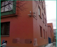
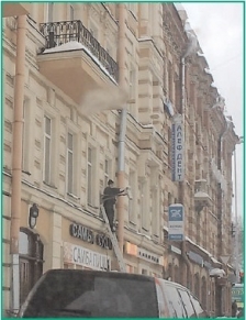


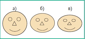

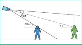
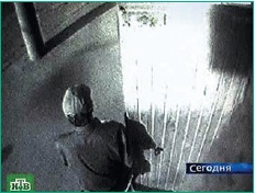
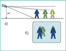
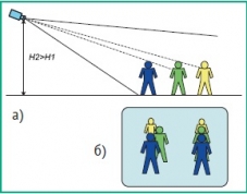
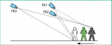
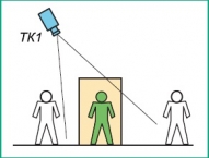
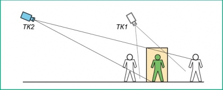

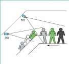
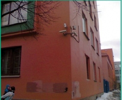


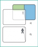
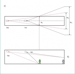 Fig. 17 Installation of TC for television control of the corridor