| SHIP'S NIGHT VISION DEVICES.
VOLKOV Viktor Genrikhovich, Candidate of Technical Sciences, Associate Professor
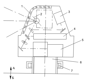
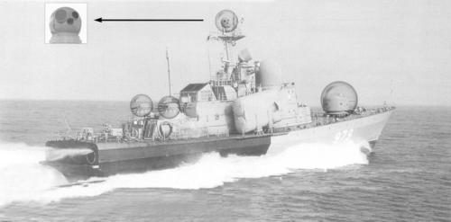
SHIP'S NIGHT VISION DEVICES (Part 2) End. Beginning in No. 1, 2006 Multichannel ship NVD systems most often include a daytime TV system, a NTFS, a TVP, as well as a laser rangefinder and a target tracking radar. Such an instrument complex is coupled with a ship's long-range detection radar. An object detected with its help is captured by the field of view of the multichannel NVD, which ensures target recognition, measurement of the range and its coordinates, aiming and guidance of weapons — guns or missiles — at the target. In the latter case, a target tracking and tracking radar or a laser guidance system is used. Multichannel systems are produced in the form of instrument complexes, structurally made of separate blocks installed on a common gyrostabilized platform, or of combined channels with partial or complete alignment of the optical axes and a common input window. The main parameters of multichannel systems (according to company prospectuses) are given in Table 1 and Table 2. Fig. 1 and 2 show the design diagrams of typical marine combined multichannel systems Volcan by SAGEM (France) (Fig. 1) and Model 975 by Kollmorgen (USA) (Fig. 2) [1].
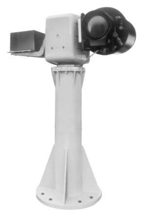
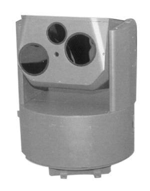
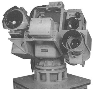
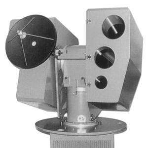
The Volcan system is designed to detect, recognize and track surface and air targets. It has an automatic tracking device, TV and TVP channels, and a laser rangefinder. All channels have a common input window with a diameter of 80 mm. The Model 975 system has the same purpose. It has not only a common input window for all channels, but also a combination of the optical axes of some channels mounted on a single gyrostabilized platform with dimensions of 600×600 mm. The platform can be placed at any point on the deck or on the mast. The system includes a unit for adjusting the optical axes of individual channels. Manual and automatic target tracking modes are provided, as well as a tracking mode set by the ship's radar.The appearance of integrated and combined NVGs is shown in photos 1, 2, respectively.
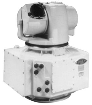
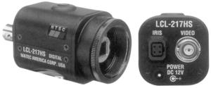
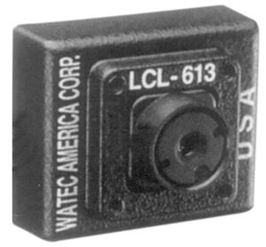
Let us consider the parameters of typical channels included in the multichannel system. NTVS and TVP have already been described [18]. The KESTREL daytime color TV system [2] (photo 3a) is based on a full-format 1/4-inch CCD matrix with 752×582 pixels. The signal-to-noise ratio is over 46 dB, the field of view angle can be smoothly adjusted within the range from 47×35 to 3×2.250. The weight of the TV camera does not exceed 2.5 kg, dimensions are W130x370 mm, power consumption is 5 W at a voltage of =9 – 32 V, the operating temperature range is from –30 to +500 C. A typical example of a modern color daytime TV camera is the LCL-217HS Watec model (photo 3b) [3]. It is based on a 1/3-inch CCD matrix with a pixel count of 795×586 and a pixel size of 6.5×6.25 µm. The sensitivity of the TV camera is 0.2 lx, the resolution is more than 480 TV lines, the working spectrum area is 0.4 – 0.75 µm, the signal-to-noise ratio is more than 50 dB, the supply voltage is 12 V, the consumption current is 140 mA, the weight is 85 g, the dimensions are 34x34x39 mm, the operating temperature range is from –10 to +400 C. The frameless color TV camera LCL-613 of 1/4 inch format from the same company [3] (photo 3c) with the number of pixels 512×582 has a sensitivity of 5 lx, a resolution of more than 330 TV lines, a signal-to-noise ratio of more than 46 dB, the supply voltage is 4.8 – 5.5 V, the consumption current is 160 mA, the weight is 20 g, the dimensions are 28x28x19 mm, the operating temperature range is from 0 to +400 C.
Modular laser rangefinders emit at a wavelength of 1.064 µm or 1.54 (1.57) µm and provide range measurements up to 40 km with an accuracy of ± 5 m [4 – 7]. A typical example of such a rangefinder is the MOLEM model from Zeiss Optronik GmbH (photo 4) [6]. This rangefinder emits at a wavelength of 1.543 µm with pulse energy of 10 mJ with a pulse duration of 5 ns and a frequency of 1 Hz. The angular divergence of the radiation is 0.5 mrad, the range of measured distances with an accuracy of 5 m is 50 — 39995 m. The target discrimination distance by range is 20 m, strobing by range is possible with a step of 10 m, weight is 2.5 kg, dimensions are 180x124x112 mm, supply voltage = 18 — 32 V, current consumption is less than 2 A, the operating temperature range is from -35 to +630 C.
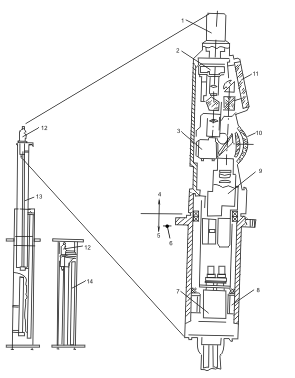
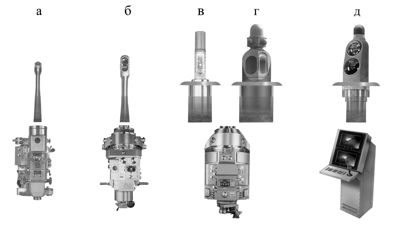
An example of a typical radar is the 9GR600 model by Celsius Tech AB (Sweden). In search mode, the radar operates in the frequency ranges of 1.01–1.11 GHz, 1.25–1.35 GHz (D-band) and 8.5–9.6 GHz (I-band). The radar weighs 1,550 kg. A gyrostabilized parabolic antenna measuring 2,700 x 700 mm and weighing 375 kg provides horizontal scanning within 3,600 and vertical scanning from 25 to +850 at a speed of up to 85 deg/s. The pulse radiation power is 200 kW at a frequency of 400 MHz. The horizontal divergence of the radio beam is 6–80 for the D-band and 20–250 for the vertical, and 1 and 30, respectively, for the I-band. The radar can detect a ship at a range of over 20 km, and a missile at a range of over 10 km. The range measurement accuracy is 45 m, and the angular coordinates are up to 0.20. Multichannel systems for submarines are enclosed in a single module that can be raised or lowered using a movable periscope mast. The module includes the radar, TV and TVP channels. Observation of the water surface is carried out from the periscope control panel with TV or ocular information output. The diagram of the construction of a typical multichannel system for a submarine periscope is shown in Fig. 3 [8, 9]. The external appearance of typical systems of this type is shown in Fig. 4 [12]. The length of the periscope is from 10 to 40 m, depending on the type of submarine.
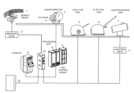
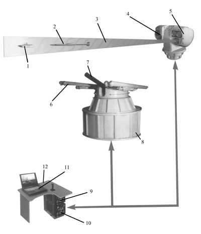
Prospects are associated with the transition to third-generation TVPs, which use focal plane arrays of photodetectors operating in the spectral range of 3–5 and 8–12 μm [15]. Multichannel systems are an integral part of the fire control systems (FCS) of naval weapons. The diagram of typical naval FCS is shown in Fig. 5, 6 [1, 17].
Further development of multichannel ship night vision devices will be the creation of fully integrated systems with automatic detection, recognition and guidance of weapons to the target. Such systems are still in the development stage.
Literature 1. Jane's Ship Weapon Control Systems, USA, 2003, p. 64. |


