Security television camera: a new solution using the optical-electronic scaling method.
Vyacheslav Mikhailovich SMELKOV,
Candidate of Technical Sciences
The paper [ 1] published a technical solution for a television camera using the optical-electronic image scaling method.
Its distinctive features are: analog principle, no loss of resolution of the enlarged image compared to the digital scaling method, and no need to use a zoom lens.
This paper addresses the problem of improving the quality of the image of a registered intruder in conditions of low illumination of a protected area by means of operational shooting of the object using an improved method of optical-electronic scaling.
Seventeen years ago, in October 1985, the French company I2S announced a new technical solution [2], which was subsequently implemented in fully solid-state cameras of the MONOSHOT series.
Translated from English, the term “MONOSHOT” means “single”, which quite accurately reflects the essence of the proposed method.
As applied to CCD matrix TV cameras, this method defines the following characteristic features of the new operating mode:
- the exposure of the photoelectric process on the CCD target or the countdown of the accumulation time of the photodetector begins at an arbitrary point in time, determined by an external trigger, i.e. it operates asynchronously with the camera synchronizer;
- the exposure time or accumulation time varies within wide limits, determined by the physical limitations of the photodetector;
- the video signal at the output is generated synchronously with the camera's synchronizing generator during one half-frame according to the television standard;
- after the accumulation time has expired, the CCD target is forcibly released from charge carriers, i.e., it is in a state of non-accumulation.”
In the “MONOSHOT” mode, the TV camera essentially becomes a device for television photography of objects of control, since it ensures their registration by means of a single formation of a video signal using a CCD image sensor.
The possibility of increasing the sensitivity of a television camera in the MONOSHOT mode by optimally selecting the CCD matrix accumulation time can be successfully implemented using the proposed improved method of optical-electronic scaling as applied to a security television camera.
This can be justified as follows.
In low light, an adequately selected exposure of the photodetector with a duration of more than one frame will inevitably lead to an increase in the inertia of the television camera, but such an effect should be recognized as acceptable, since clear contours of moving objects cannot be obtained in principle due to photon noise that affects these conditions.
According to the new method, the CCD accumulation time in the television photography mode is set automatically by the video signal, therefore the method is called MONOSHOT–ZOOM-AUTO”.
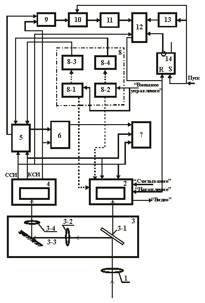
The structural diagram of the television camera according to the new method is shown in Fig. 1.
The camera contains a first lens (1), a single-shot video signal sensor (2), a beam splitter (3), a television signal sensor (4), a frame signal generator (5), a switching unit (6), a pointing unit (8), a switch (9), a peak detector (10), an analog-to-digital converter (ADC) (11), an accumulation duration generator (12), a single-shot multivibrator (13), and an RS trigger (14).
Fig. 1. Structural diagram of the television camera
Note that the camera module in MONOSHOT mode is used as the sensor (2), and the camera module in television mode (TV mode) is used as the sensor (4).
The video control unit (VCU) is shown at number 7 in the diagram.
The input signal “reading” and the output signal “video” for the sensor (2) are the signals for interfacing with the computer.
The optical scaling factor of the beam splitter (3) is determined by the ratio of the frame size of the lens (1) to the corresponding size of the sensor photo target (2).
On the other hand, as in [ 1], the dimensions of the electronic frame and the raster sizes X and Y are related by the relationship:
a = X/Km,
b = Y/Km,
where a and X are the horizontal dimensions of the frame and the raster,
b and Y are the vertical dimensions of the frame and the raster, respectively.
Let's consider the operation of a television camera
The optical image of the observed scene along the optical path: first lens (1), translucent mirror (3-1), collective lens (3-2), reflective mirror (3-3), second lens (3-4) is projected onto the sensor target (4).
At the same time, a fragment of this image, enlarged in accordance with the scaling factor of the beam splitter (3), is projected along another optical path: the first lens (1), a semi-transparent mirror (3-1) onto the photo target of the sensor (2).
The image on the photo target of the sensor (4) is then converted into a video signal according to the television standard, and the output frame (F) and line (L) sync pulses as leading ones implement the slave synchronization mode of the frame signal generator (5), sensor (2) and VCU (7).
The generator (5) generates an electronic frame signal at the output, the geometric dimensions and position in the raster of which determine the selection of the above-mentioned fragment of the presented input image.
A mixing signal comes from the output of the unit (6) to the “video” input of the VCU (7), the components of which are the video signal from the sensor (4) and the frame signal from the generator (5).
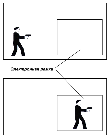
On the VKU screen (7) a normal image of the observed scene and an image of a rectangular (electronic) frame displaying the selected fragment are reproduced.
Note that drives (8-1) and (8-2) guide the sensor (2) horizontally and vertically, respectively, and position sensors (8-3) and (8-4) control the movement of the rectangular frame in the raster along these coordinates.
For remote targeting of the selected shooting object, drives (8-1) and (8-2) must be connected to the “External control” bus.
A special feature of the proposed solution is the linear dependence of the video signal from the “video” output of the sensor (4) on the illumination, i.e. the g-characteristic is equal to 1, as well as the absence of the effect of automatic gain control (AGC) on this output.
Until the pulse signal arrives at the “Start” input, a high logical level is present at the “accumulation duration setting” input of the sensor (2), therefore the sensor (2) is in the non-accumulation state. The TV image generated by the sensor (4) and the image of the rectangular frame superimposed on it are reproduced on the VKU (7) screen.
The RS trigger (14) is in the “1” state at the inverse output. Due to this, the accumulation duration generator (12), implemented on the basis of multi-stage counters, is blocked at the carry input by a high logical level and therefore does not count the clock SSI.
Let us assume that the object of the shooting is the figure of a moving person when he appears in the zone designated by the electronic frame.
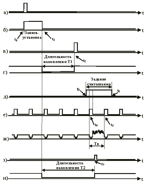
In this case, the operator, based on the observed television image, applies a control pulse to the “Start” input of the television camera (Fig. 2a) at the moment t0, shown in Fig. 3b. Then the RS trigger (14) goes into the “0” state via the inverse output. At the same time, the start pulse resets the peak detector (10) and starts the monostable multivibrator (13).
The monostable multivibrator (13) generates a pulse signal at the output (Fig. 2b), the duration of which t0…t1 is the resolution interval of the preliminary recording-installation operation in the counters of the generator (12).

Fig. 2. Timing diagram explaining the operation of the television camera

Fig. 3. Images from the VKU screen, explaining television control of filming
Electronic frame
Note that the time interval t0 … t1 is quite small and can be neglected when assessing the time of processes.
Starting from the moment t0, the peak detector (10) starts measuring and storing the current value of the video signal from the output of the switch (9). Note that the switch (9) measures and stores the video signal generated by the sensor (4), but within the limits limited in the raster by the electronic frame.
The constant voltage from the output of the peak detector (10), proportional to the maximum value of the measured video signal, is then converted in the ADC (11) from analog to digital form and fed to the setup inputs of the shaper counters (12).
By the moment t1 (Fig. 2b), the recording and installation of this number in the counters of the generator (12) must be completed.
Starting from the moment t1, the counters of the generator (12) count the increment of data, and a low logical level is set at the output of the block (12) (Fig. 2d). Therefore, the sensor (2) goes into the state of accumulation of information charges. The duration of accumulation in the sensor (2) is set to be optimal according to the criterion of the maximum signal-to-noise ratio of the video signal of the taken picture, which is achieved by preliminary calibration of the TV camera.
After the end of charge accumulation in the sensor (2), the counters of the shaper (12) are reset and the RS trigger (14) is set to the 1” state at the inverse output. The counters of the shaper (12) are set to zero, and at the moment t2 of the end of the exposure, at the input of the sensor accumulation task (2), the logical “0” level is replaced by the logical “1” level (Fig. 2g).
Next, the charge relief of the information frame (more precisely, a half-frame according to the television standard) is transferred from the photo target (accumulation section) to the storage section of the sensor (2), and its photo target goes into the “non-accumulation” state.
Let us assume that at the subsequent moment t3 (Fig. 2d) at the “reading duration assignment” input of the sensor (2), the logical “0” level is replaced by the logical “1” level.
When the high level in the signal for setting the reading duration” coincides with the end of the nearest frame blanking pulse (see moment t4 in Fig. 2e), reading of the charge relief of the information frame begins, which continues during the interval t4 … t5.
As a result, an electrical signal of a single frame is formed at the output of the “video” sensor (2), and consequently at the output of the television camera (Fig. 2g).
Note that the duration of this signal, taking into account the frame blanking pulse, is Tk = 20 ms and corresponds to the period of half frames according to the television standard.
Let us consider the calibration procedure.
The camera is presented with an image of a test chart, the illumination of which in white (Emax) ensures the formation of the maximum amplitude of the video signal generated by the sensor (4), i.e. its compliance with the criterion of the maximum signal-to-noise ratio.
Next, the value of the voltage input through the setup inputs to the generator counters (12) is adjusted so that when the maximum count is reached and the output carry pulse appears from the most significant digit, the accumulation duration of the sensor (2) is one half-frame according to the television standard, i.e. Tk.
Then, if the illumination of the filming object E1 is less than Emax, then when the maximum count is reached, the output carry pulse will appear later, at the moment t2 (Fig. 2c), and the accumulation duration of the sensor (2) will be T1 > Tk.
If the illumination of the object being photographed decreases further, i.e. E2 < E1, then proportionally later, at the moment t7 (Fig. 2z), a transfer pulse will appear, and the accumulation duration T2 will increase accordingly (Fig. 2i).
It should be noted that the automatic selection of the maximum accumulation time Tmax of the sensor (2) should take into account the physical limitations of the CCD photodetector for dark current. For an uncooled CCD photodetector, it can be assumed that Tmax = 10 s and take this factor into account when selecting the capacity of the shaper counters (12).
It is obvious that the ratio Tmax/Tk determines the value of the maximum gain in energy sensitivity for the proposed solution of the television camera in comparison with [ 1]. On the other hand, the factor of increasing the contrast sensitivity of the image of the photo, equal to the optical scaling factor, is retained.
It should be noted that the quality of the image of the registered intruder is improved without the use of expensive electron-optical converters designed to increase the brightness of the optical image on the photodetector target. There is also a refusal to accumulate video frames in the computer memory.
We will add that, compared to computer accumulation, the “charge accumulation” on the photo target used in this solution provides significantly less noise and distortion of the video signal.
For security television systems that include a motion detector, another operating tactic can be proposed. Based on the television image of the scene being observed, the electronic frame is installed in the automatic control zone of the responsible object. Then, in the event of an “intra-frame” change in the video signal, the motion detector generates an alarm signal, which in turn generates a pulse on the “Start” bus. As a result, a high-quality television image of the intruder is taken.
In conclusion
The author hopes that this technical solution for a security television camera will be in demand. If this happens, then the words of Nobel laureate D. Gabor will once again be confirmed: “The future cannot be foreseen, but it can be invented.”
Literature
1. Smelkov V. M. Television camera for covert surveillance and automated security//Special equipment, 2001, No. 3, pp. 20 – 23.
2. Application of France No. 2589301 from 10/28/85 IPC H04N3/15, 5/238. Electronic obturation device.
Applicant – I2S (France).

Добавить комментарий