Все про видеонаблюдение
Все про умный дом
Все о пожарной безопасности
Сейчас читают
 Как ускорить и смотреть ютуб без тормозов и замедленияЕсли Вы на этой странице, то Вам, скорее всего, […]
 10 лучших прогрессивных языков программирования для разработки мобильных приложенийЗнаете ли вы, что мобильные приложения — это не только […]
 6 важных особенностей, которые следует учитывать при строительстве нового домаСтроительство нового дома – это уникальная возможность […]
Гороскоп на Сегодня
PROTECTION OF AUXILIARY TECHNICAL MEANS AND SYSTEMS FROM SPEECH INFORMATION LEAKAGE.
Anatoly Anatolyevich KHOREV, Doctor of Technical Sciences, Professor
PROTECTION OF AUXILIARY TECHNICAL MEANS AND SYSTEMS FROM SPEECH INFORMATION LEAKAGE
For the discussion of restricted access information (meetings, discussions, conferences, negotiations, etc.), special rooms (offices, assembly halls, conference rooms, etc.) are used, which are called dedicated, or protected, rooms.
Dedicated rooms often have auxiliary technical means and systems (ATMS) installed, which are not directly used to process confidential information.
These are, as a rule, analog and digital telephone sets of management and city PBXs, loudspeakers of the warning system, single- and three-program receivers, secondary electric clocks, sensors of security and fire alarm systems, etc.
If the connecting lines of the VTSS go beyond the boundaries of the controlled zone, then it is possible to intercept conversations conducted in designated areas via acoustoelectric (passive and active) information leakage channels.
The most common of these VTSS are telephone sets of city automatic telephone exchanges.
A telephone set has several elements that have the ability to convert acoustic vibrations into electrical ones, i.e., have a “microphone effect”.
These include: a ringing circuit, a telephone and, of course, a microphone capsule.
Due to acoustoelectric transformations in these elements, information (dangerous) signals arise.
When the receiver is hung up, the telephone and microphone capsules are galvanically disconnected from the telephone line, and when special highly sensitive low-frequency amplifiers are connected to it, it is possible to intercept dangerous signals that arise in the elements of the ringing circuit only.
The amplitude of these dangerous signals, as a rule, does not exceed fractions of a mV.
When using the “high-frequency imposition” method to retrieve information, despite the galvanic disconnection of the microphone from the telephone line, the imposition signal, due to the high frequency, passes into the microphone circuit and is amplitude-modulated by the information signal.
Consequently, both the ringing circuit and the microphone circuit must be protected in the telephone set.
Passive, active and combined methods and means are used to protect the telephone set from leakage of acoustic (speech) information via the acoustoelectric channel.
The technical characteristics of some means of protection are given in Table 1 [1 – 5]. Both passive and active means of protection have their own characteristic advantages and disadvantages.
The advantages of passive means of protection are:
- relative simplicity of the electrical circuit and small dimensions;
- they do not require power sources;
- they are included in the break of the VTSS circuits and therefore the failure of some elements of the electrical circuit is detected during operation;
- relatively low cost.
Active protection devices, compared to passive ones, are built on a more complex scheme and, therefore, have a higher cost.
They require the use of electrical power during operation. However, active protection devices are usually more effective.
Combined protection devices are built on the basis of a combination of passive and active devices.
The most widely used passive protection methods include:
- limiting low-amplitude signals;
- filtering high-frequency signals (high-frequency interference signals);
- disabling signal converters (sources).
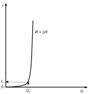
The ability to limit low-amplitude signals is based on the nonlinear properties of semiconductor elements, mainly diodes.
The low-amplitude limiter circuit uses two back-to-back diodes (a diode bridge) with a volt-ampere characteristic (the dependence of the value of the electric current flowing through the diode on the voltage applied to it) shown in Fig. 1.
Such diodes have a resistance for low-amplitude currents of hundreds of kOhm, and for high-amplitude currents (useful signals) — units of Ohm or less, which eliminates the passage of dangerous low-amplitude signals into the telephone line and has virtually no effect on the passage of useful signals through the diodes.
Diodes with an opening voltage of 0.1 — 0.2 V are usually installed in protection circuits.
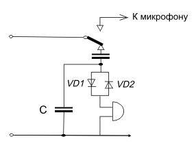
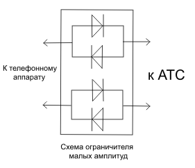
Diode limiters are connected in series to the bell line (Fig. 2a) or directly to each of the telephone lines (Fig. 2b).
Fig. 1. Volt-ampere characteristic of diodes used in low-amplitude limiter circuits
a)
b)
Fig. 2. Installation of diode limiters in the electric bell line (a) and telephone line (b)
The simplest products that implement the method of limiting low-amplitude signals include the Korund protection device for analog two-wire telephone sets (TA) [2, 4].
The diode limiters of the device provide suppression of low-frequency signals of low amplitude (Uc ? 50 mV) at a frequency of 1 kHz towards the subscriber line (ATS) by more than 60 dB.
When conducting telephone conversations, the device has virtually no effect on the quality of the conversation (attenuation of speech signals is less than 2 dB).
The “Korund” protection device has small dimensions (40x13x10 mm) and is installed inside Euro sockets and uninterruptible sockets of the RTSh-4 type.
The method of filtering high-frequency signals is used mainly to protect telephone sets from “high-frequency interference”.
The simplest filter is a capacitor C, installed in the ringing circuit of telephone sets with an electromechanical ringer (Fig. 2a) and in the microphone circuit of all sets (Fig. 3) [1].
The capacitance of the capacitors is selected to be such as to shunt the high-frequency signal supplied to the line and not to have a significant effect on the quality of telephone conversations.
Usually, capacitors with a capacity of 1 μF are used for installation in the ringing circuit, and capacitors with a capacity of 0.01 μF are used for installation in the microphone circuit [1].
A more complex filtering device is a multi-link LC low-pass filter (Fig. 4) [1].
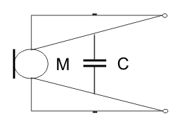
Fig. 3. Installing capacitor C in the microphone circuit
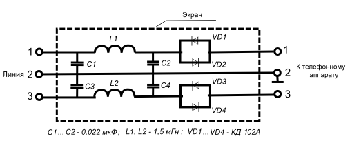
Fig. 4. Schematic diagram of the “Granit-8” two-wire line protection device
To protect telephone sets from information leakage via acoustic-electric channels, devices that combine a low-pass filter and a low-signal limiter are usually used. Such devices include: devices such as “Granit-8” and others.
The Granit-8 protection device is designed to provide protection of speech information from leakage via acoustoelectric channels through two-wire lines of open telephone networks, radio broadcasting networks, director and dispatch communication systems and is designed for round-the-clock operation in automatic mode under continuous load in lines with a resistance of 600 Ohm ±10%.
The basic diagram of the Granit-8 protection device is shown in Fig. 4 [1].
The device is a four-terminal network consisting of two U-shaped inductive-capacitive links and two diode bridges [3].
The diode bridge of the circuit is the input of the product and is designed to suppress low-frequency signals of small amplitude that occur in the telephone set during acoustoelectric transformations (the insertion attenuation in the speech signal frequency band of 0.3 — 4 kHz at an input signal level of Uc ? 100 mV towards the subscriber line (PBX) is not less than 60 dB) [3].
The output element of the four-terminal network is a U-shaped LC low-pass filter. The filter is designed to suppress high-frequency signals fed to the line by “high-frequency imposition” equipment (the insertion attenuation at a frequency of 100 kHz at an input signal level of Uc = 5 V towards the telephone set is not less than 10 dB) [3].
In the frequency range from 150 Hz to 10 kHz, the attenuation of speech signals (Uc = 5 V) does not exceed 3 dB and therefore does not have a significant impact on the quality of communication.
Structurally, the device can be made in various versions. Photo 1 shows the product «Granit-8», made in a metal case, in which the printed circuit board of the product is fixed under the cover of the case.
Photo 2 shows the appearance of the Granit-VIII protection device, in which all circuit elements are protected by an electrostatic screen.
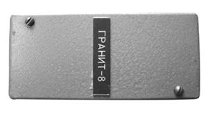
a) — top view;
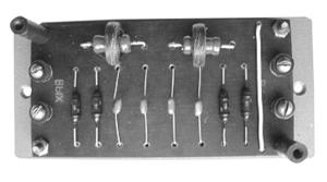
b) — view with the cover removed
Photo 1. External appearance of the Granit-8 protection device
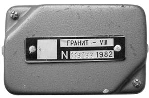
a) — view from above;
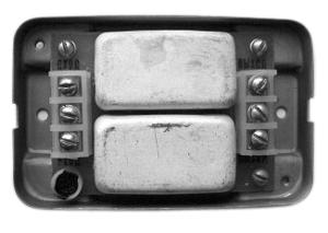
b) — view with the cover removed
Photo 2. External appearance of the Granit-VIII protection device
The device is connected to the break in the telephone line using terminals located on the printed circuit board. The outer terminals (photo 2) are intended for connecting telephone wires, and the central ones are for connecting the ground.
When installing the device, it is extremely important to connect it correctly to the telephone line: the telephone wire coming from the telephone set is connected to the “input” terminals, and the telephone line going to the PBX is connected to the “output” terminals.
If the device is connected incorrectly, it will not protect the telephone set from information leakage via the active acoustoelectric channel (when using the “high-frequency imposition” method to intercept information).
Disconnecting signal converters (sources) from the line when the telephone receiver is hung up is the most effective method of protecting information.
The simplest way to implement this method of protection is to install a special manual switch in the telephone housing or telephone line.
More convenient to use is to install a special protection device in the telephone line that automatically (without operator intervention) disconnects the telephone from the line when the telephone receiver is hung up.
Typical devices implementing this protection method include the “Barrier-M1” two-wire telephone line protection device.
It consists of [5]:
- an electronic switchboard;
- a circuit for analyzing the telephone set’s status, the presence of ringing signals, and controlling the switchboard;
- a circuit for protecting the telephone set from exposure to high-voltage pulses.
The device operates in the following modes: standby, call signal transmission and working.
In standby mode (with the telephone receiver in place), the telephone set is disconnected from the line, and the device is in the mode of analyzing the position of the telephone receiver and the presence of call signals.
In this case, the isolation resistance between the telephone set and the PBX line is at least 20 MOhm. The voltage at the device output in standby reception is 5 — 7 V [5].
When receiving call signals, the device switches to the call signal transmission mode, in which the telephone set is connected to the line via an electronic switch. The connection is made only for the duration of the call signals.
When the telephone handset is lifted, the device switches to the operating mode and the telephone set is connected to the line.
The device switches from standby to operating mode when the current in the telephone line is at least 5 mA [5].
The device is installed in a break in a telephone line, usually at its exit from a dedicated (protected) room or in a distribution board (cross) located within the controlled area.
The device is powered from a telephone line with a standby current consumption of no more than 0.3 mA [5].
The “Barrier-M1” device provides protection of the telephone not only from information leakage via an acoustoelectric channel, but also from the effects of high-voltage pulses (up to 1,000 V and up to 100 μs in duration) [5].
The MP-8 “Sigma-RA” protection device also implements an information protection method based on disconnecting signal converters (sources) from the line, and is designed for continuous round-the-clock operation [4].
The operating principle of the device is based on the mechanical disconnection of the telephone set from the appropriate telephone line of the analog PBX in the “standby” mode (with the telephone receiver in the “hold” position).
When the subscriber lifts the telephone handset from the hooks, the telephone contacts are connected to the telephone line, which ensures a two-way conversation.
The “call” signal (ring) comes from the telephone line to a special autonomous circuit of the device through an optoelectronic isolation.
This ensures one-way transmission of signals from the telephone line and absolutely eliminates any information leakage from the premises through the telephone line (with the telephone handset in call waiting mode, the input resistance of the device from the PBX side tends to infinity (R ® ?)).
The device is designed as a separate unit, which is connected to the telephone set with a short cable (up to 15 cm), and to a European socket with a long cable (~ 1.5 m).
The device has an autonomous power source (a 12 V microbattery, which is installed inside the unit). A special indicator [4] is used to monitor the battery's performance.
The MP-7 «Gvard» protection device [4] is used to protect digital PBX telephone sets.
When the telephone handset is hung up, the device disconnects from the line not only the microphone and the telephone handset, but also the microphone and speaker of the loudspeaker (SSP), which eliminates the possibility of listening to conversations in the room by an internal subscriber of the PBX when using the acoustic control function of the room (often called “police mode”), implemented on all digital mini-PBXs.
Active methods of protection against information leakage via an acoustoelectric channel involve feeding a masking signal (most often, a “white noise” type) of the speech frequency range (as a rule, the main interference power is concentrated in the frequency range of a standard telephone channel: 300 — 3,400 Hz) into the line when the telephone receiver is put on.
When the telephone receiver is removed, the noise signal is fed into the line. The “Granit-12” noise generator is one of the devices implementing active protection methods.
The most frequently used protection devices are combined types that implement several protection methods simultaneously. Such devices include, for example, the MP-1A and MP-1C protection devices [4].
The MP-1A and MP-1C protection devices are designed to protect subscriber line telephones of analog and digital automatic telephone exchanges, respectively, in call waiting mode from information leakage via passive and active acoustoelectric channels.
They simultaneously use both passive and active protection methods.
The devices contain a noise generator, nonlinear circuits and a low-level signal suppression unit.
They are distinguished by their small dimensions (32x15x13 mm) and low power consumption compared to the closest prototypes such as “Granit-8,11,12”, which allows them to be placed inside telephone sockets [2, 4].
The insertion attenuation towards the subscriber line (PBX) in the speech frequency band for low-level signals is no less than 68 dB for the MP-1A, and no less than 43 dB for the MP-1C.
In this case, the current consumption is not less than 0.42 A [4].
In the call waiting mode, a noise signal with an amplitude of not less than 32 mV in the ranges of 0.02 — 30 kHz for MP-1A and 0.02 — 300 kHz — for MP-1C [4] is fed into the telephone line. The acoustic sensitivity of the devices is not more than 0.1 μV/Pa.
To protect the receivers of the city retransmission network, the loudspeakers of the warning system, the protection devices MP-2 and MP-5 [4] are used.
The MP-2 protection device is designed to protect information from leakage over the broadcast network during acoustic impact on a three-program receiver.
The device contains a noise generator, a control unit and a relay, which ensures the introduction of a noise signal into the broadcast circuit, as well as disconnection of the receiver from the broadcast network when the supply voltage disappears.
The presence of a noise signal is monitored using a LED, which goes out when the noise signal disappears.
The MP-2 device has overall dimensions of 51x56x13 mm and a weight of no more than 70 g [4].
The MP-5 protection device (analogous to “Granit-9”) is designed to protect public address system loudspeakers or single-program receivers from leakage of speech information through them via acoustoelectric channels.
The MP-5 device contains: a loudspeaker connection unit to the line, which is triggered upon receipt of an information message, an analyzer of the signal coming to the input, and a control unit.
In the absence of alert signals (or broadcast signals), the loudspeaker is disconnected from the line using relay contacts.
When an alert signal is received, the loudspeaker is connected to the line (the response time of the product upon receipt of an information signal is no more than 5.0 ms).
The time it takes to maintain the connected state of the loudspeaker during pauses is from 1 to 9 s.
With these parameters, the MP-5 device does not affect the quality of the message [4].
When the loudspeaker is switched off, the device provides suppression of electrical signals in the frequency band of 0.02 — 10 kHz, arising due to the acoustoelectric conversion of acoustic signals, before they enter the transmission line by at least 90 dB [4].
The acoustic sensitivity of the device is no more than 0.1 μV/Pa.
The device can be powered from an external 12 V source and/or a Krona battery.
The continuous operation time of the device from one “Krona” type battery when receiving an information signal is at least 100 hours. The device has overall dimensions of 120x55x23 mm and a weight of 0.2 kg [4].
To protect secondary clocks from leakage of speech information through them via acoustoelectric channels, protection devices of the “Granit-6” type (photo 3), MP-4, etc. are used.
The MP-4 protection device (analogous to Granit-6) contains a noise generator and a control circuit, which are used to introduce a noise signal into the secondary clock circuit and to control its presence [4].
The optical control circuit is triggered every 2 minutes and indicates correct operation by briefly lighting the LED.
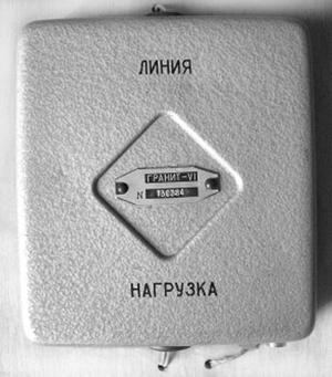
a) — view from above;
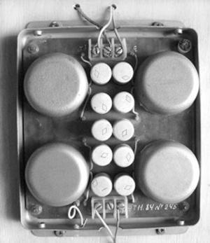
b) – view with the cover removed
Photo 3. External appearance of the Granit-6 protection device:
The noise signal voltage at the device output in the speech frequency band without load is at least 50 mV.
The device is powered by a built-in galvanic battery. The current consumed by the device does not exceed 70 μA. The device has overall dimensions of 84x60x20 mm and a weight of no more than 0.3 kg [4].
Literature
- Gavrish V.F. Practical guide to protecting commercial secrets. Simferopol: Tavrida, 1994, p. 112.
- Eliseev A.A. Means of protecting low-current lines. Special equipment, 2000, No. 1, pp. 9 – 12.
- Protection equipment: Catalog. St. Petersburg: PPSh Laboratory, 2005, p. 14.
- Devices for protecting low-current lines: Catalog. renom.ru
- Device for protecting telephone lines “Barrier-M1”. Operating instructions. Moscow: TOO “Ensanos”, 1998, p.
Table 1. Main characteristics of devices for protecting auxiliary technical means
|
Name (type) |
Purpose |
Protection methods |
  ;
Power supply |
Note |
|||
|
Signal limitation |
RF interference signal filtering |
Converter shutdown |
Line noise pollution |
||||
| “Korund” | Analog two-wire TA protection |
yes |
no |
no |
no |
not required |
Suppression of low-frequency signals of small amplitude (Uc Ј 50 mV) at a frequency of 1 kHz towards the subscriber line (PBX) by at least 60 dB. Attenuation of speech signals is less than 2 dB. Dimensions 40x13x10 mm. It is installed inside Euro sockets and unbreakable sockets of the RTSh-4 type |
| “Granit-8” | Protection of analog two-wire TA |
yes |
yes |
no |
no |
not required |
Designed for round-the-clock operation in automatic mode under continuous load in lines with resistance of 600 Ohm ± 10%. Insertion loss in the speech signal frequency band of 0.3 — 4 kHz at an input signal level of Uc Ј 100 mV towards the subscriber line (PBX) is not less than 60 dB. Insertion loss at a frequency of 100 kHz at an input signal level of Uc = 5 V towards the telephone set is not less than 10 dB. In the frequency range from 150 Hz to 10 kHz, the attenuation of speech signals (Uc = 5 V) does not exceed 3 dB |
| “Barrier-M1” | protection of analog two-wire TA |
no |
no |
yes |
no |
from subscriber line |
The isolation resistance between the telephone set and the PBX line is at least 20 MOhm. The voltage at the device output in standby reception is 5 — 7 V. The device transitions from standby to operating mode when the current in the telephone line is at least 5 mA. Current consumption in standby mode is no more than 0.3 mA |
| MP-1A (analog “Granit-11,12”) | protection of analog two-wire TA |
yes |
no |
no |
yes |
from subscriber line |
Overall dimensions are 32x15x13 mm. Insertion loss towards the subscriber line (PBX) in the speech frequency band is at least 68 dB for MP-1A. Current consumption is at least 0.42 A. Noise signal voltage is at least 32 mV in the range of 0.02 — 30 kHz. |
| MP-1C | protection of digital two-wire TA |
yes |
no |
no |
yes |
from subscriber line |
Overall dimensions 32x15x13 mm. Insertion loss towards subscriber line (PBX) in speech frequency band is not less than 43 dB for MP-1A. Current consumption is not less than 0.42 A. Noise signal voltage is not less than 32 mV in range 0.02 – 300 kHz |
| MP-7 “Gvard” | protection of digital two-wire telephone sets |
no |
no |
yes |
no |
from the subscriber line |
When the telephone handset is hung up, the device disconnects the microphone and telephone handset, the microphone and speaker of the loudspeaker (SSP) from the line |
| MP-8 “Sigma-RA” | protection of analog two-wire TA |
no |
no |
yes |
no |
main – from subscriber line; backup – from 12 V battery | Input electrical resistance module in call waiting mode is infinity. Current consumption from 12 V battery in the following mode: conversational — 0 mA; call waiting — 0 mA; call — no more than 5 mA; number dialing — no more than 3 mA; with the line disconnected, TA connected and the handset lifted — no more than 30 mA. Direct current consumed from the line in call waiting and hang-up mode is 0 mA. Alternating current consumed from the line by the calling device is no more than 3 mA. The level of the called signal at a distance of 0.5 m is not less than 83 dB |
| MP-2 | protection of a three-program receiver of a broadcasting network |
no |
no |
yes |
yes |
from the broadcasting network |
Overall dimensions of the product are 51x56x13 mm, weight is not more than 70 g |
| MP-5 (analog of “Granit-9”) | protection of public address system loudspeakers or single-program receivers of the public address network |
no |
no |
yes |
yes |
from an external 12 V source and/or a Krona battery | The response time of the product upon receipt of an information signal is no more than 5.0 ms. The time of maintaining the connected state of the loudspeaker during pauses is from 1 to 9 s. Suppression of electrical signals in the frequency band of 0.02 — 10 kHz is not less than 90 dB. The continuous operation time of the device from one “Krona” battery when receiving an information signal is at least 100 hours. Overall dimensions are 120x55x23 mm, weight is 0.2 kg. |
| MP-4 (analog “Granit-6”) | secondary clock protection |
no |
no |
yes |
yes |
from an external 12 V source and/or a “Krona” battery | The noise signal voltage at the device output in the speech frequency band without load is at least 50 mV. The current consumption is no more than 70 μA. Overall dimensions are 84x60x20 mm, weight is no more than 0.3 kg |


Добавить комментарий