Night observation devices.
VOLKOV Viktor Genrikhovich, Candidate of Technical Sciences, Associate Professor
Modern special equipment widely uses night observation devices for work in the twilight and at night.
These include night vision devices based on image intensifier tubes (IITs), low-level television (TV) surveillance devices, active-pulse night vision devices, thermal imaging and combined surveillance devices [1].
Night vision devices based on IITs can be made in the form of:
1. night vision goggles;
2. head-mounted monoculars;
3. night monoculars;
4. night bino-, pseudo- and bioculars.
Devices of the first two directions were considered in detail in the work [2]. In this regard, this article will discuss only the 3rd and 4th directions.
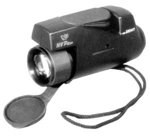
The main parameters of night monoculars are presented in Table 1. They can be made in the form of hand-held portable (photo 1) or tripod-mounted portable (photo 2) devices.
These devices can have a rangefinder scale [3] allowing a rough estimate of the distance to the object of observation (Fig. 1) or can be made according to the scheme of a rangefinder device [4 – 6].
In particular, the FORMS (Forward Observers Ranging and Marking Scope) device (model 30 for civilian use) [4] is a combination of a night monocular with a laser rangefinder based on a semiconductor laser emitter.
The device weighs 570 g, the detection range of a human figure is 180 m at a natural night illumination level of 10-3 lux, the field of view is 400, and the magnification is 1x.
The continuous operation time of the device reaches 30 hours at a supply voltage of 3 V.
The laser rangefinder channel provides range measurements of up to 5 km with an accuracy of up to ±5 m.
The laser emitter has a divergence angle of 0.5 mrad in rangefinding mode and 300 in illumination mode.
The range data in digital form is displayed in red against the green background of the glow of the image intensifier screen.
Night binocular observation device-rangefinder N/CROS MK II with a built-in compass from International Technologies (Lasers) Ltd. (Israel) [4] (table 2) (photo 3) contains a laser rangefinder channel based on a semiconductor laser with a wavelength of 0.904 µm, a radiation power of 4 W and an angular divergence of 1.5 mrad.
This channel measures the range from 20 to 2000 m with an accuracy of ±1 m (up to 200 m), ±2.5 m (200-500 m), ±5 m (over 500 m) with a measurement time of up to 0.5 s.
The built-in digital compass makes it possible to determine the direction with an accuracy of up to ±0.50 within ±350.
The N/BIS-3 night pseudo-binocular device from the same company also has a digital compass, which allows you to determine the direction within ±180 with the same accuracy.
a) ZENIT NV-piezo
(RF, JSC “Krasnogorsk Plant named after S.A. Zverev”);
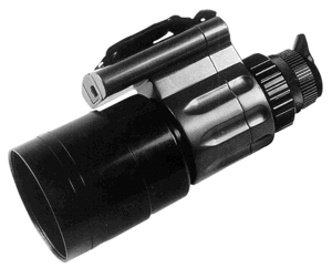
b) PN 6 (Republic of Belarus, Belomo);
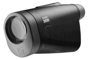
c) 5.6×60 N (Germany, Carl Zeiss);
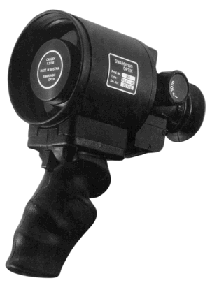
g ) NS-B 4-80 (Austria, Swarovski Optik KG);

e) Sonic 2.5×42 26-0300 (Bushnell, USA)
Photo 1. Wearable monoculars:
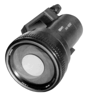
a) ZENIT NV-1000 (RF, JSC “Krasnogorsk Plant named after S.A. Zverev);
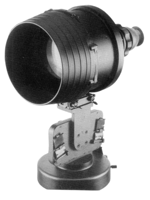
b) W401 (Great Britain, Hall and Watts Ltd.);

c) EAGLE (Great Britain, Pilkington PE Ltd.)
Photo 2. Portable night observation devices.
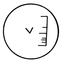
Fig. 1. External appearance of the rangefinder
scale of the night observation device
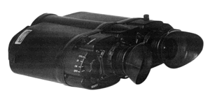
Photo 3. Night binocular observation device –
rangefinder N/CROS MK II from
International Technologies (Lasers) Ltd. (Israel)
Table 1. Main parameters of night monocular observation devices (according to company brochures)
The Bushnell company (USA) [20] developed an original first-generation night monocular Sonic 2.5×42 26-0300 (photo 1d) with a built-in microphone, which allows detecting objects by sound at a distance of up to 82 m.
The device has a viewing range of 183 m, a field of view of 15°, a magnification of 2.5x, a power supply of 3 V, a weight of 482 g, and dimensions of 170 x 95 x 70 mm.
However, the presence of an additional rangefinder channel complicates the device and increases its cost. In this regard, a night rangefinder device was developed that does not have a photoreceiver, which is typical for a laser rangefinder channel.
In addition, the device provides protection against light interference.
The diagram of such a device is shown in Fig. 2. To protect against light interference, a chain of elements 9 12 is used.
When the device is exposed to light interference, a signal is generated in the IOP circuit 2, which passes through the separating capacitor 9 to the input of the low-pass filter 10.
Capacitor 9 is needed to cut off the constant voltage supplied to the screen 5 from the VIP 8, and the low-pass filter 10, tuned to the specified signal, suppresses all other interference.
Then the signal is amplified in the UI 11and goes to the switch 12, which drops the voltage from the MCP 4, locking it for the duration of the interference.
Compared to a conventional night device, such a device has a degree of protection against light interference higher than 100 times.
To measure the range, the ZGI 13 is turned on.
It starts the BN 14, which excites the ILPI 15 with current pulses.
The latter generates radiation pulses that are collimated using OFI 16 and directed at the object of observation, creating an illumination spot within its contour.
The radiation of the ILPI, reflected from the object, enters the objective 1, which creates an image of the spot superimposed on the image of the object.
Simultaneously, when the illumination pulse reflected from the object impacts the EOP 2, a pulsed electrical signal is generated in its circuit, which passes through the capacitor 9 to the input of the LPF 10.
The latter cuts off all extraneous interference, and the useful signal passes through it, is amplified in the UI 11 and is fed to the input of the IVI 17.
A pulse signal comes to its other input at the moment of BN 14 startup from the ZGI 13.
The IVI 17 measures the interval between these two signals, which corresponds to the distance to the object.
The IVI 17 represents this interval in digital form and transmits it to the ID 18, the LED indicator of which displays the range value in meters.
The device has a field of view of 480, a human figure recognition range of 200 m at a natural night illumination level of 10-3 lux, a magnification of 1x, a weight of 350 g, and a range measurement accuracy of ±1 m at a distance of up to 5 km.
The divergence of the laser radiation in range-finding mode is 1.30, and in illumination mode — from several degrees to 400 [5, 6].
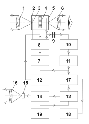
Fig. 2. Scheme of constructing a night observation device-rangefinder:
1 — objective, 2 — image intensifier, 3 — photocathode, 4 — microchannel plate (MCP), 5 — screen, 6 — eyepiece, 7 — primary power source (PPS), 8 — high-voltage power source (HVPS), 9 — separating capacitor, 10 — low-pass filter (LPF), 11 — pulse amplifier (PA), 12 — switch, 13 — master pulse generator (MPG), 14 — pump unit (PU), 15 — ILPI, 16 — radiation formation objective (RFO), 17 — time interval meter (TIM), 18 — range indicator (RI), 19 — frequency divider (FD)
For devices mounted on a tripod, it is possible to measure angles in the vertical and horizontal planes using the tripod limb scales with an accuracy of 0-01.
An original technical solution was the use of a built-in piezoelectric transducer in monoculars as a power source, allowing the device to be used without conventional power elements, for example, the Zenit NV-320 (piezo) (photo 1a), Cyclop P (table 1) devices.
However, devices of this type have not found wide distribution.
Night monoculars have minimal weight and dimensions, but are inconvenient from the point of view of long-term observation.
Night binoculars, in which observation is carried out simultaneously with both eyes, are more effective.
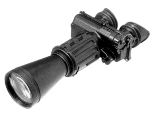
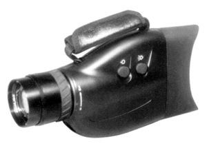
There are binocular devices (table 2, photo 4), pseudo-binocular (table 3, photo 5) and biocular (table 4, photo 5).
Binocular devices have two identical night channels for the right and left eyes of the observer.
Pseudo-binocular devices have one objective, one image intensifier and a pseudo-binocular optical system that distributes the image from the image intensifier screen to both eyes.
Biocular devices also have one objective, one image intensifier and one eyepiece, a biocular magnifying glass, which has such a large exit pupil diameter that it covers both eyes of the observer.
Like night monoculars, binoculars can be held in the hands (photo 4) or mounted on a tripod with the ability to measure the distance to an object, its coordinates and orientation, as described above.
The main parameters of binocular devices are given in Table. 2.
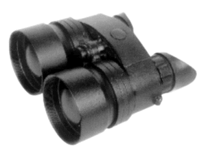
a) AN-1 with mirror-lens lenses) (RF, State Unitary Enterprise PA Refinery);

b) LUNA-TRON Type 904 (Infrarot-Technik Gmbh., Germany)
Photo 4. Night binocular observation devices:
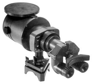
a) BIF2-6B (Switzerland, Wild Heebrugg Ltd.);
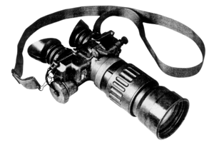
b) F5010 (USA, ITT);
c) Baigish 25 (Tatarstan, JSC KOMZ)

d) Baigish 6u (Tatarstan, OJSC KOMZ);

e) D-3M (Belarus, NPF Dipol);
e) ZENIT NV BN-10
(RF, JSC Krasnogorsk Plant named after S.A. Zverev)
Photo 5. Observation devices: pseudo-binocular and biocular.
Table 2. Main parameters of night binocular observation devices (according to company prospectuses)
Table 3. Main parameters of night pseudo-binocular observation devices (according to company prospectuses)
Table 4. Main parameters of night binocular observation devices (according to company brochures)
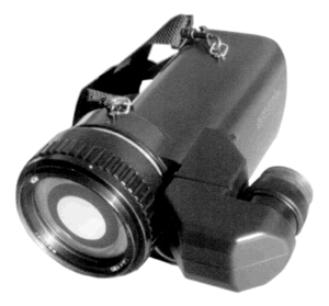
Both monoculars and binoculars of the “day/night” class can be used [2] (photo 6).
In particular, the night monocular device Zenit NV-500 (RF, JSC “Krasnogorsk Plant named after S.A. Zverev”) (photo 6a) contains day and night observation channels. For the “day” and “night” modes, respectively, the magnification is 5.7x and 5.7x, the field of view angle is 100 and 6.60, the resolution is 10.5″ and 75″.
The range of recognition of a full-length human figure in the night channel, equipped with a mirror-lens objective, at the level of natural night illumination is 750 m, weight — 3 kg, dimensions — 282x222x155 mm.
Binoculars «day/night» BDN (RF, JSC ZOMZ) (photo 6b) have for the «day» and «night» modes respectively a magnification of 7 and 2x, a field of view of 6.5 and 8.80, a resolution of 8 and 100′, a weight of 1.33 kg and dimensions of 175x204x75 mm.
a) ZENIT NV-500
(RF, JSC Krasnogorsk plant named after . S.A. Zvereva);
b) – BDN (RF, OJSC ZOMZ)
Photo 6. Day/night observation devices.
Night vision devices can operate in natural night illumination on the ground from 10-3 (clear starry night) to twilight (tenths of lux).
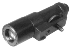
For operation on very dark nights (cloudy starry night or mountain gorges) and in complete darkness, devices can be equipped with infrared (IR) illuminators.
Their typical parameters are given in table 5, and their appearance is shown in photo 7 [7].
A common drawback of all these devices is the impossibility of remote image transmission, as well as the need for close eye contact between the operator and the device, which causes fatigue.
Table 5. Main parameters of infrared illuminators for night vision devices (according to company brochures)
a) DI-2 for the ZENIT NV-piezo device
(RF OJSC “Krasnogorsk Plant named after S.A. Zverev”);
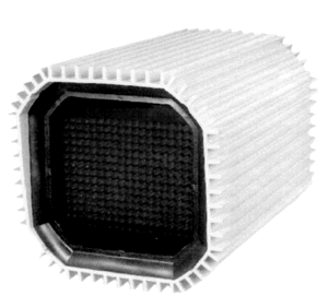
b) CSI-IR (Canada, CANTRONIC Systems Inc.);
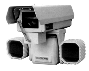
c) the same illuminator together with a low-level TV system
Photo 7. Infrared illuminators for night surveillance devices.
Television (TV) surveillance devices are free from this drawback, providing round-the-clock operation, remote transmission of images, the ability to duplicate them for several operators simultaneously, and observation from a TV monitor screen [8].
The latter can be removed from the operator's face at a considerable distance, which reduces fatigue during long-term observation.
The main parameters of TV surveillance devices are given in Table 6, and their appearance is shown in Photo 8.
Due to the presence of an image intensifier at the input of TV devices, the image quality is lower than that of the night vision devices discussed above.
With the use of ultra-high-sensitivity TV cameras, a real opportunity has arisen to abandon the image intensifier and thereby overcome this drawback [8].
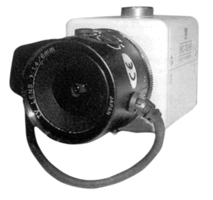
In particular, the SCC-B2003P and SCC-B2303P TV cameras from Samsung (Japan) in 1/3-inch format with a resolution of 480 TV lines can operate at an illumination of 0.004 lux (color mode) or 0.001 lux (black and white mode) [19]. In recent years, TV devices have appeared that operate in the spectrum region of 1–2.2 μm instead of the traditional regions of 0.4–0.9 or 0.4–1.1 μm [9].
Comparative parameters of such devices are given in Table 7, and the appearance is in photo 9.
Thanks to the new working range of the spectrum, these devices have a number of advantages over traditional TV devices and night vision devices [9]: the ability to work both in normal and in low-transparency atmospheres, unmasking low-contrast objects, when exposed to light interference.
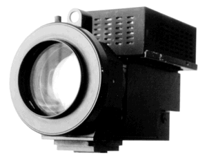
a) Cerberus-13 (RF, SKB MKE SB RAS);
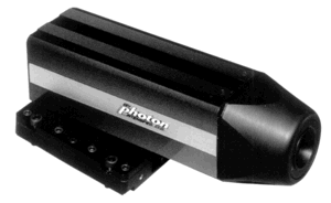
b) Photon (Great Britain, EEV);
Photo 8. Night television surveillance devices using an image intensifier tube (IIT) at the input of the television camera.
c) VNC-702 (RF, EMU) [8];

d) SCC-B2003P (Japan, Samsung) [19]
Photo 8. Night television surveillance devices without an image intensifier tube at the input.
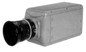
Photo 9. Television surveillance device for the spectrum range of 1 – 2.2 μm
Table 6. Low-level television cameras (according to company brochures)
Table 7. Main parameters of television systems operating in the spectrum range of 0.9 – 2.0 μm (according to company brochures)
The same properties are possessed by active-pulse night vision devices, which can have an ocular or TV image output and also provide precise measurement of the distance to the object of observation.
The operating principle of such devices, their capabilities and the main parameters of typical models are described in the works [1, 10].
An example of such devices is the “Argus-AI” model (photo 10) [11].
Its range in passive mode is 350 m, in active-pulse mode — up to 500 m, the field of view angle in passive mode is 100, in active-pulse mode 30.
The laser illuminator generated an average radiation power of 35 mW at a wavelength of 820 — 850 nm at a frequency of 50 — 5000 Hz.
The supply voltage of the device was = 12 V with a power consumption of about 7 W.
The depth of the zone viewed in depth was 25.75 m with a maximum electronic vision zone of up to 995 m.
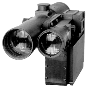
Photo 10. Active-pulse night observation device “Argus-AI”
Thermal imaging devices operate in a wide range of changing external conditions. These devices are described in the work [12].
Here we will limit ourselves to describing those samples of devices that are used for observation.
Their main parameters are summarized in Table 8, and their appearance is given in Photo 11.
In Photo 11eIn particular, the ultra-miniature thermal imaging camera Omega with a temperature resolution of at least 40 mK [18] is shown.
Table 8. Main parameters of thermal imaging surveillance devices (according to company brochures)
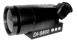
a) DI-9800 (USA, Digital Imaging Infrared Inc.);
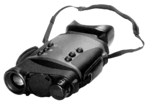
b) – MATIS (France, SAGEM);
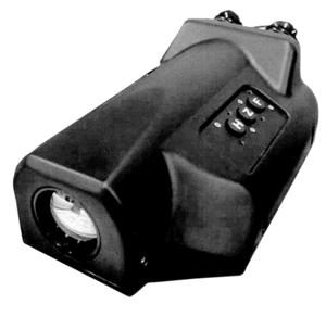
c) CT3G, ( Italy, Galileo Avionica);
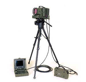
d) ASIR (Turkey, ASELSAN);

d) “RAKURS” (RF, [17]);
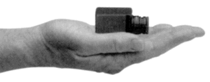
e) Omega (USA, L.O.T. Oriel Ltd .)
Photo 11. Thermal imaging surveillance devices.
It should be noted that these devices are multifunctional: they can measure the temperature in the image of the observed objects both at individual points selected using a laser marker, and in specified areas of this image, or the average temperature value for the entire image.
The disadvantage of the devices is their relatively high cost and the dependence of the image quality on the level of temperature contrasts of objects with the surrounding background.
In connection with this, combined observation devices have appeared, combining several channels that differ in the physical principle of construction [1, 13, 14].
The devices can be held in hands (photo 12a), mounted on a tripod (photo 12b) or on a mobile carrier [13].
In any case, individual channels are selected so that the disadvantages of one channel are compensated by the advantages of another.
As a result, the device can provide round-the-clock and all-weather surveillance, and the laser rangefinder channel allows for high-precision measurement of the distance to the object of observation.
An example of such a device is the HURRICANE model from OPGAL (Israel) [14].
The surveillance device, mounted on a tripod or installed on a vehicle, contains a TV channel and a thermal imaging channel.
The TV channel is based on a CCD matrix with 768×494 elements, operates in the spectrum range of 0.4 – 0.7 µm, has a field of view of 5.6×4.20, a human detection range of over 2500 m and a human recognition range of over 1000 m.
The thermal imaging channel is based on a microbolometer matrix with 320×240 elements, operates in the spectrum range of 8–12 µm, has the same field of view, with a temperature contrast of 20 C, the human detection range is over 1500 m, and the human recognition range is over 800 m.
Most often, surveillance devices are combined with a laser rangefinder (photo 12b).
Photo 12b shows the SIMRAD LP8G device (Norway, Simrad Optronics A/S).
It combines the KN 200 night channel [2], a laser rangefinder [4], and a digital goniometer.
The prospects for the development of such devices are associated with the possibility of image processing [15, 16] (photo 13).
The Okhotnik and Buk systems provide image processing in real time without thinning out video information in order to improve the visibility of television and thermal imaging images in unfavorable visibility conditions: haze, fog, snowfall, rain, smoke and light interference.
The systems allow to increase the detection and recognition range of objects in such visibility conditions by 1.3 – 1.7 times. The sizes of the processed images: 768×576 decomposition elements for the entire frame, 384×256 decomposition elements for the zone of interest.
Provides increased global and local contrast, normalization of average brightness, emphasis on the contours of small objects, reduction of fluctuation and noise interference, smooth electronic scaling of images from 1 to 4 times, overlay of graphic information, adaptation of parameters and algorithms to the channel type, automatic adaptation to specific observation conditions.
Promising functions of the systems include integration of information from various channels and electronic stabilization of the field of view.
Automatic tracking of detected objects with the issuance of their current coordinates and control signals to the actuator drives is possible.
In the Okhotnik system, the tracking window provides adaptive adjustment to the object size in the range from 2×2 to 256×256 decomposition elements.
The algorithms allow working with multi-contrast, maneuvering objects on non-uniform backgrounds, tracking of the object when optical communication is interrupted for up to 5 seconds with prediction based on the Kalman filter, automatic detection of loss of tracking and automatic additional acquisition of the object caused by the interruption of optical communication.
The weight of the “Okhotnik” system is 4–6 kg, the volume is 5–7 liters.
The weight of the “Buk” system does not exceed 2.2 kg, dimensions are 208x130x74 mm, power consumption is 30 W when powered from =27 V.
These systems allow to minimize the psychophysical load on the operator and create favorable conditions for automation of the observation process.
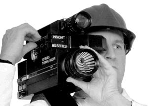
a) held in hands:
INSIGHT 80 SERIES THERMAL IMAGING CAMERA SYSTEM
(UK, Insight Vision Systems Inc.) [13];
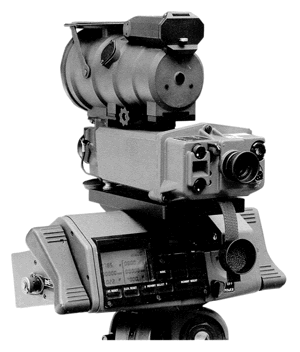
b) mounted on a tripod: SIMRAD LP8G (Norway, Simrad Optronics A/S)
Photo 12. Combined night observation devices.

Photo 13. Buk image processing units
Literature.
1. Geykhman I.L., Volkov V.G. Fundamentals of improving visibility in difficult conditions. Moscow, Nedra-Business Center, 1999.
2. Volkov V.G. Head-mounted night vision devices.//Special Equipment, 2002, No. 5, pp. 2 – 15.
3. Medvedev A.V., Grinkevich A.V., Knyazev S.N., Morozov S.S. Night rangefinder device on a biplanar direct transfer image intensifier tube. Optical Journal, 2001, No. 10, pp. 70-72.
4. Volkov V.G. Portable laser rangefinders.//Special equipment, 2001, No. 6, pp. 2 — 13.
5. Veselovsky I.A., Volkov V.G., Tokarev A.N., Assonov A.S. Night vision device. Certificate for Utility Model of the Russian Federation No. 18780 for application No. 2001101344 with priority dated 22.01.2001.
6. Assonov A.S., Veselovsky I.A., Volkov V.G., Koshchavtsev N.F., Reztsov D.N., Tokarev A.N. Night vision devices with range measurement function. The Defense Complex – Scientific and Technical Progress of Russia, 2001, No. 4, pp. 23–27.
7. Volkov V.G. Laser illuminators and target designators for night vision devices.//Special equipment, 2002, No. 2, pp. 2 – 10.
8. Volkov V.G. Ultra-high-sensitivity television systems.//Special equipment, 2002 2, pp. 2 – 10.
9. Volkov V.G. New generation night vision devices.//Special equipment, 2001, No. 5, pp. 2 – 8.
10. Volkov V.G. Active-pulse night vision devices.//Special equipment, 2002, No. 5, pp. 2 – 12.
11. Catalog of devices. KTI Prikladnoy Microelectronics SB RAS. RF, Novosibirsk, 2003.
12. Volkov V.G., Kovalev A.V., Fedchishin V.G. Thermal imaging devices of the new generation.//Special equipment, 2001, No. 6, pp. 16–21, 2002, No. 1, pp. 18–24, 26.
13. Volkov V.G. Multichannel night vision devices for ground use.//Special equipment, 2001, No. 2, pp. 13–20.
14. HURRICANE Integrated Electro-Optical Observation System. OPGAL company brochure, Israel, 2002.
15. Image processing system “OKHOTNIK”. Prospect of the State Ryazan Instrument-making Plant. RF, Ryazan, 2003.
16. Video Image Enhancement System “BUK”. Prospect of the State Ryazan Instrument-making Plant. RF, Ryazan, 2003.
17. Low-Level Television Cameras. Catalogue of the Company JSC “RUSELEKTRONIKA-NV”. RF, M., 2002.
18. Thermal Imaging Camera. EUROPHOTONICS, 2003, Vol.8, No. 2, p. 39.
19. New Television Cameras from Samsung. CCTV info, 2003, No. 0, p. 5.
20. Night Vision Gen 1. Catalogue of the Company Bushnell, USA, 2003.


Добавить комментарий