Multichannel software-controlled electron-optical complexes for high-speed recording of a series of images of a fast-moving process.
Mikhail Ilyich Krutik
The article presents the principles of constructing software-controlled complexes for ultra-high-speed shooting of fast-moving processes.
The basis of such devices are electron-optical converters (EOC) with nanosecond shutter control modules, providing recording of a sequence of frames with exposure times of up to 10-8 s.
Such systems can provide synchronous multi-frame shooting (a series of images from two to eight frames) of optical processes with an adjustable period between frames from 10 ns to 1 ms or more.
The results of using one of these systems in problems related to research in the field of ballistics are presented.
When conducting research in the field of fast-flowing processes, the method of synchronous high-speed shooting is often used.
The use of pulsed electron-optical converters (EOC) for these purposes makes it possible to create equipment that provides single-frame and multi-frame high-speed shooting with exposure times of up to nanoseconds and intervals between frames of up to tens of nanoseconds.
Various electron-optical cameras (EOC) and entire software-controlled complexes are built on the basis of such EOCs and high-voltage nanosecond control modules.
The latter are of interest where remote control of camera parameters is required (exposure time, start delay, gain factor of the image intensifier, etc.).
This need arises in cases where the operator's presence in the work area is not allowed, but at the same time, operational changes in camera parameters from experiment to experiment are required.
This is of particular interest in studies related to ballistics.
The task of obtaining images of an object flying at high speed (a projectile, a bullet, etc.) at various points of the trajectory, the length of which can reach hundreds of meters, requires the installation of several EOCs at a significant distance both from each other and from the place where the recorded frames are processed.
Under such conditions, the advantages of remotely programmable systems are even more obvious. From his workplace, the operator sets the necessary parameters for each EOC, controls the operation of all devices included in the complex and the process of recording images itself.
In addition, the conveniences associated with the use of software-controlled EOCs will find application in other areas of science and technology, even if all the equipment and the object of study are located nearby.
In addition to the listed advantages, this principle of constructing the complex provides for the setting of an unprecedentedly large number of possible values for each of the EOC parameters — up to 2000 combinations for exposure time and start delay value, and up to 256 for setting the sensitivity of the photoelectron channel.
Introduction
The use of EOC as a high-speed electronic shutter began in the mid-50s.
Over the years, quite a few publications have been published that reflect the issues of developing and using EOC, as well as devices based on them, in various fields of science and technology.
In order not to refer the reader, who is not sufficiently familiar with the image intensifier and the electronic shutter mode, to specialized literature, a brief description of them is given below.
Only one of the existing types of image intensifier is presented, on the basis of which programmable complexes were created.
Of all currently existing electron-optical converters, the so-called flat IOPs (proximity focus image intensifiers) of generations II, II+ and III are of the greatest interest for use in devices for high-speed recording of images of fast-moving processes.
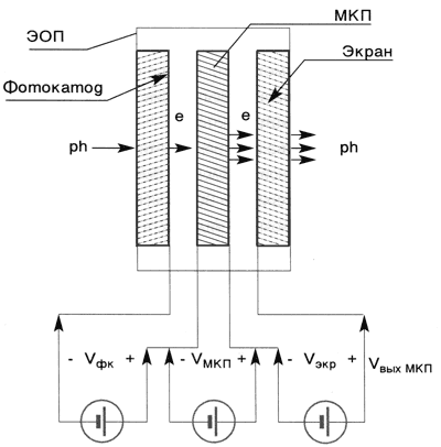
Their indisputable advantage is their small size, high and uniform spatial resolution across the field, complete absence of geometric distortions and high immunity to external electromagnetic interference. The diagram of a flat IOP is shown in Fig. 1.
Fig. 1. IOPs of generations II and III.
This image intensifier is a vacuum block with three electrodes arranged parallel to each other inside.
The first is a semi-transparent photocathode (multi-alkali for generation II and gallium arsenide for III), applied to the inner surface of the input glass window. A microchannel plate (MCP) is installed behind it. The last electrode is a screen, which is a thin layer of a special phosphor applied to the glass output window. When switched on, the corresponding voltages are applied between the electrodes.
In Fig. 1, the voltage on the EOP electrodes ensures its operation in the so-called “static mode.” In this mode, it is open and operates simply as an image amplifier.
The image of the object is projected onto the inner surface of the input glass window and the photocathode, under the influence of the flow of radiation quanta, emits a corresponding flow of electrons.
The electric field formed by the power source Vфк,transfers them to the input of the MCP, which amplifies the electrons by Ke times (proportional to the voltage VMCP applied to it).
The amplified electron flow from the output of the MCP, entering the accelerating field formed by the power source Vekr, falls on the screen of the EOP and causes the corresponding radiation.
The gain coefficient of the EOP (KEOP), equal to the ratio of the radiation power level from the EOP screen to the radiation power level incident on the photocathode, is determined by the voltage applied to the MCP (VMCP). The dependence of KEOP on the voltage on the MCP is shown in Fig. 2.
As a rule, the gain of the EOP can be set within the range from 1 to 30,000 – 50,000.
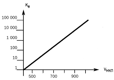
Fig. 2. Dependence of the electron gain
on the voltage on the MCP.
Image intensifier as an electronic shutter
From Fig. 1 it is clear that the electrons during their movement pass through three sections, each of which has its own accelerating electric field. These are the photocathode – MCP input”, “MCP input – MCP output and “MCP output – screen”. Theoretically, any of these sections can be used for pulse control (strobing) of the image intensifier.
Turning off any of the power sources (Vфк, VMКП or Vэкр) transfers it to a permanently closed state. Applying a voltage pulse with the appropriate polarity and amplitude to the de-energized gap leads to the opening of the image intensifier tube for a time equal to its duration.
In practice, only the first two sections are used: “photocathode – MCP input” and MCP input – MCP output”.
The screen gap would require pulses with an amplitude of 5…6 kV for control, versus several hundred volts for the first two, which, all other things being equal, would lead to unreasonably large dimensions of the control module.
Another condition makes strobing only by the gap «photocathode — MCP input» preferable. The fact is that in the standby mode, when controlling by the gap «MCP input — MCP output», through the open gap «photocathode — MCP input» electrons generated by the photocathode under background (daylight) and pulsed (flash lamp) irradiation continue to bombard the input surface of the MCP. With prolonged exposure to large electron flows, the microchannel plate can emit residual gases that sharply reduce the service life of the image intensifier (the photocathode is «poisoned», constantly glowing dots appear, etc.).
That is, it must be handled in the same way as when using it in night vision devices — do not allow significant background light flux to hit the photocathode. If this condition is met, then strobing by MCP can be successfully applied.
Unfortunately, for many tasks these requirements are not feasible. First of all, this concerns such a field of research as ballistics.
The experiments are conducted in the daytime, and the duration of the pulsed illumination can be thousands of times longer than the duration of the shutter pulse.
Since the flash lamp must provide the power required to obtain a certain number of photons during the exposure time necessary to form the corresponding image, all its remaining energy creates only an additional electron load at the MCP input.
When strobing along the photocathode – MCP input gap in the off state, electrons do not reach the MCP at any level of photocathode irradiation.
This mode allows working in bright daylight conditions even at the maximum gain of the image intensifier (but not higher than required for the pulse mode).
For the strobed mode, the duration of the pulse that unlocks the image intensifier determines the exposure time of the frame, and the number of photons falling on the photocathode during this time determines the energy value of the recorded image.
The corresponding number of photons is emitted on the screen in proportion to the gain of the image intensifier. Due to the inertia of the phosphor, the time during which they are emitted can significantly exceed the exposure time.
In pulse systems, this does not matter.
The main thing is that they all get to the multichannel photodetector (CCD or CMOS) of the television image recording system in the interval corresponding to the charge accumulation phase.
Currently, there are circuit solutions that ensure the construction of shutter modules with a controlled duration texp from 5 nanoseconds to hundreds of microseconds and more.
Such a range ensures the registration (ultra-high-speed photography) of objects flying at a speed significantly exceeding the first cosmic (8,000 m/s).
For comparison, light travels a distance of 1 m in 3 ns.
Fixed-pulse-width schemes (based on ultra-fast switching of distributed-parameter lines) provide minimum gating times of tens of picoseconds, but they are not considered in this article.
High-frequency properties of image intensifier tubes are a separate issue. Serial image intensifier tubes produced by various manufacturers were usually designed for night vision devices, which did not require such characteristics.
Therefore, in some cases, these image intensifier tubes require significant modification.
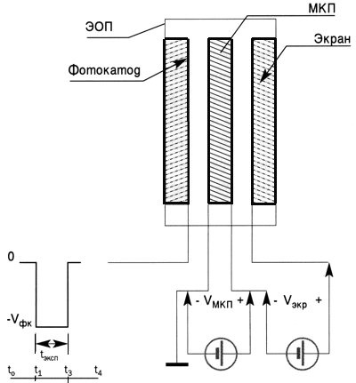
Fig. 3. Pulse control of generation II and III image intensifier tubes.
Principles of constructing multichannel software-controlled image intensifier tubes
The structure of the complex is usually determined by its purpose.
Shooting at short exposures requires active illumination of the object, which is usually performed by flash lamps (sometimes powerful pulse lasers are also used).
The flash lamp is triggered by a signal from the photosensor synchronously with the moment the object appears in the field of view of a certain channel of the complex.
Precise adjustment of the shutter module response delay determines the shooting moment and is selected from the estimated time of the object's appearance at a given point.
In addition, the use of the complex for shooting objects whose movement can occur at different speeds requires the ability to change the exposure time within a fairly wide range.
As an example, Fig. 4 shows a single-channel programmable recording system.
It includes:
- electron-optical camera (EOC), consisting of an electron-optical converter (EOC) with a shutter module, which perform the functions of an ultra-fast shutter and an image intensifier; 2/3″ high-resolution digital CCD camera (1280 x 1024);
- pulse flash lamp (FL);
- photo trigger device, consisting of a laser (L) and a photosensor (PD);
- industrial computer (PC).
After switching on the system, the operator sets all the parameters of the complex in the EOC software module using special software.
They ensure the registration of the object image and its recording in the computer memory.
These parameters include:
- the delay value of the start of the pulse flash lamp;
- the delay value of the response of the shutter pulse generator in the EOC;
- shutter pulse duration values (exposure time);
- image gain value of the image intensifier tube (voltage on the MCP).
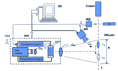
Fig. 4. Structural diagram of a single-channel software-controlled electron-optical camera as part of a test complex.
After leaving the barrel, the object interrupts the laser beam.
In this case, the photosensor FD generates sync pulses 1 and 2 to start the flash pulse lamp IL and the electron-optical camera EOC. By the time t a, when the object appears in the field of view of A camera, they are started.
Image of the object through the input lens Oin is projected onto the photocathode of the image intensifier tube, the shutter of which at this moment opens for a time t exp. The electrons emitted from the photocathode form a certain charge, which, amplified in the MCP by Ke times, causes an optical flash of the corresponding energy on the image intensifier tube screen.
In some ballistic tasks, in addition to the single exposure mode, the double exposure mode can be very useful.
It consists in the fact that after the shutter of the image intensifier is triggered at the moment t a, after a preset delay, the shutter is triggered again at the moment t b, to which the object, remaining in the camera's image field, will move (Fig. 4).
In this case, two images of one object, spaced across the field, will be formed on the image intensifier screen.
A necessary condition for this mode is the absence of reflected light from various surfaces (walls, structural elements) located in the image field.
From the image intensifier screen through the projection lens Opr is transferred to the photosensitive area of the digital CCD camera, which, also operating in standby mode, has by this point switched to charge accumulation mode.
The accumulation time is selected to be slightly longer than the afterglow time of the image intensifier phosphor.
During this time (for the P-20 phosphor it is 3…5 ms), all signal photons are accumulated, and further accumulation «collects» only background noise.
After this, the video data is digitized into a 10-bit code and, via a user-programmable gate array, is sent to transceivers operating on a twisted pair cable.
Depending on the test conditions, it may be more convenient to use fiber-optic communication lines or a radio channel.
Data exchange between the camera and the PC occurs via an image input board (frame grabber) with a PCI bus.
In addition, this configuration ensures very high sensitivity of image recording.
At the maximum gain, it is tens of photons per resolvable image element in the plane of the EOC photocathode.
Based on the presented single-channel system, it is possible to build multi-channel complexes with a virtually unlimited number of cameras.
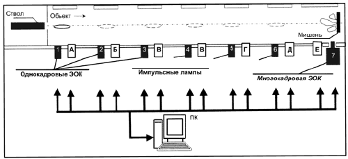
An example of a multi-channel software-controlled complex is shown in Fig. 5.
It includes:
1) 1ё 6 single-frame EOCs (similar to the one shown in Fig. 3);
2) A ё E – pulse flash lamps;
3) multi-frame EOC.
4) PC – industrial computer that programs all components of the complex, records and processes the recorded information.
In this list, a new component is the multi-frame EOC (see Fig. 6), which is a block of eight electron-optical channels, onto the inputs of which images of the object under study are projected through one common input lens and a prism splitter of the light beam into eight.
Each of the eight channels is similar in structure to the EOC shown in Fig. 4.
When a trigger pulse is received at the camera input, a sequence of frames is recorded at precisely specified moments in time and with precisely specified exposure time.
A sequence of eight recorded frames is transmitted to an industrial computer via a communication cable.
A special image input controller (on the PCI bus) ensures that frames are recorded into RAM.
Fig. 5 Ballistic track and instrument complex
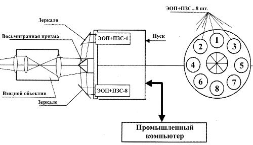
Fig. 6. Single-block programmable multi-frame EOC.
The entire complex is launched at the moment the object leaves the barrel using a special synchronization module (not shown in the figure). The synchronization pulse is sent to all EOCs 1 ё EOC 7 and pulse lamps (A ё E), and they are launched sequentially in accordance with the set time delays.
They are determined based on the expected time of the object's appearance in the field of view of the corresponding cameras. The parameters of the multi-frame camera are also selected based on the expected duration of the object's destruction process during its interaction with the target.
The advantage of using such systems is that, based on the described components, systems with different numbers of cameras can be easily assembled depending on specific requirements.
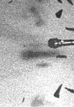
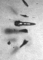
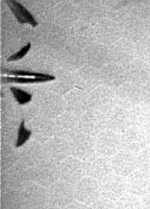
Photos 1 and 2 show the results of high-speed shooting obtained using the programmable four-frame electron-optical complex NANOGATE–Frame 4.
Photo 1 shows a series of three frames of the object's decay process as it moves along a trajectory at a speed of approximately 1000 m/s.
The intervals between frames are 200 μs (between the first and second frames) and 120 μs (between the second and third frames). The exposure times for each frame are indicated under the photograph.
 |
 |
 |
| t1 = 0 texp= 50 ns |
t2 = 200 µs texp=200 ns |
t3 = 320 µs texp=300 ns |
|
Photo 1. A series of three frames recorded by the NANOGATE–Frame 4 complex. |
||
Photo 2 is a single shot of a tracing object moving along a trajectory at a speed of approximately 800 m/s. The shot was taken with an exposure of 300 ns. In both cases, the object was illuminated by a pulsed flash lamp.
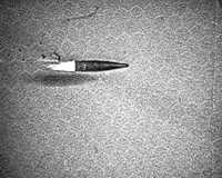
tэксп=300 ns
Photo 2. Single shot of a tracing object moving along a trajectory at a speed of approximately 800 m/s
In conclusion, I would like to note that multichannel software-controlled electron-optical complexes can find wide application in such areas as:
- interaction of pulsed laser radiation with matter;
- pulsed fluorescence;
- plasma physics;
- vibration.
In short, wherever there is a need to record the dynamics of fast processes in a wide spectral range.
Literature.
1. Butslov M.M., Stepanov B.M., Fanchenko S.D. Electron-optical converters and their application in scientific research, Moscow: Nauka, 1978.
2. Iznar A.N., Electron-optical devices, Moscow: Mashinostroenie, 1977.
3. Proceedings of the international conferences “High Speed Photography, Videography and Photonics” 1970 – 2000.
4. Proceedings of the All-Union conferences on high-speed photography and photonics. 1972 – 2001.
5. M.I. Krutik, V.P. Mayorov, V.V. Popov, M.S. Semin. Programmable nanosecond electron-optical camera NANOGATE-GC-1, “NPK VIDEOSCAN”. Abstracts of reports at the 19th All-Russian Conference on High-Speed Photography and Photonics., Moscow, 2001.
6. M.I. Krutik, V.P. Mayorov, V.V. Popov, M.S. Semin. Programmable 4-frame nanosecond electron-optical complex NANOGATE–Frame 4, “NPK VIDEOSCAN”. Abstracts of reports at the 19th All-Russian Conference on High-Speed Photography and Photonics, Moscow, 2001.
7. V. G. Komar, D. Yu. Son, M. S. Semin, V. P. Mayorov, S. A. Sabo, S. V. Belyaev, L. M. Balyasny, M. I. Krutik, O. A. Lyubich, V. L. Kotlyar, V. E. Lapotenko. Three-dimensional multi-angle glasses-free color television system with a holographic screen//Cinema and Television Technology, No. 4, 1998.

Добавить комментарий