Modernization of night vision devices.
ARKHUTIK Stepan Trofimovich,
VOLKOV Viktor Genrikhovich, Candidate of Technical Sciences, Associate Professor,
ZAYTSEVA Elena Ivanovna,
SALIKOV Vyacheslav Lvovich,
UKRAINSKY Sergey Alekseevich
Night vision devices (NVD) are widely used in special equipment to ensure observation and aiming at dusk and at night. At the same time, there is a problem of continuous improvement of their parameters.
This problem can be solved in two ways:
— development of new NVDs;
— modernization of existing serial NVDs.
The first way allows to achieve significant qualitative improvements of NVD parameters, but it is quite expensive and requires significant time expenditures. The second way allows, at first glance, to achieve more modest results, but leads to the solution of many problems with minimal expenditure of financial resources and time.
This is especially evident in relation to night vision devices for armored vehicles (BTT) [1]. Many serial BTT objects are equipped with night vision devices based on zero-generation electron-optical converters (EOC). Such night vision devices include the TPN-1 gunner's night sight installed on T-55, T-62, T-64 tanks,
T-72, TPN-3 gunner's night sight (T-72, T-80 tanks), and the BPK-2 combined day/night sight (BMP-2 infantry fighting vehicle).
Generation 0 image intensifier tubes with an oxygen-silver-zinc photocathode allow NVDs to operate only in active mode (with IR floodlight illumination), and those with a multi-alkali photocathode (except for low-sensitivity photocathodes) — only in passive mode (without illumination). Meanwhile, NVDs should operate mainly in passive mode and only on particularly dark nights — in active mode. Generation 0 image intensifier tubes have a sufficiently high resolution only in the central part of the field of view.
At the edge of the field of view, the resolution drops by 4-5 times in relation to the center [2]. Due to the limited permissible dimensions for placing the NVD in the internal cavity of the armored vehicle objects, only single-chamber image intensifiers with a low brightness gain coefficient have to be used for the above-mentioned NVD.
This circumstance, combined with the low sensitivity of the zero-generation image intensifier photocathodes, sharply limits the range of vision.
In this regard, NVDs with such EOPs provide vision only during 40% of the entire dark time of the day. Zero-generation EOPs have low noise immunity to the effects of light interference radiation (shot flashes, explosions, etc.).
This radiation illuminates the entire field of view of the NVD. The only way to combat light interference is to turn off the NVD during their exposure.
The brightness of the EOP screen depends on the level of natural night illumination (ENI). The dimensions of the zero generation EOP are relatively large. Their only advantage over the older generation EOPs is the lowest cost. However, this advantage does not compensate for all the listed disadvantages of these EOPs.
In this regard, the modernization of the NVD should be associated primarily with the replacement of the zero generation EOP with the most advanced serial EOPs of generations II+ and III.
These image intensifiers, due to their higher sensitivity of the photocathode and significant brightness gain (Table 1), provide an increase in the range of vision of night vision devices when operating in passive mode by 1.5 — 2.5 times, while ensuring this range during more than 90% of the dark time of the day.
The resolution of these image intensifiers is higher and evenly distributed over the entire field of view.
Due to the high sensitivity of the photocathode in the IR region of the spectrum, the image intensifiers allow the operation of night vision devices in both passive and active modes.
The built-in automatic brightness control circuit of the image intensifier tube ensures the constancy of the screen glow brightness in a wide range of changes in the ENO level.
The presence of microchannel plates in the image intensifier tube allows to a certain extent to localize the emission of light interference in those areas of the field of view where they occur, without causing illumination of the entire field of view of the night vision device.
This allows maintaining continuity of observation when exposed to a number of light interferences.
The dimensions of these image intensifier tubes are significantly smaller than those of the zero generation image intensifier tubes.
This allows for successful integration into the dimensions of serial NVDs when replacing the image intensifier tube.
Maintaining the same dimensions, connection dimensions, installation units and communication mechanisms of the basic serial NVDs allows for comparatively simple modernization.
Its cost will be 30–40% of the cost of developing new NVDs, despite the higher cost of generations II+ and III NVDs.
Generation III image intensifiers have a higher photocathode sensitivity than generation II+ image intensifiers, which provides a 20% increase in the range of vision in particularly dark nights. However, their cost is 3-4 times higher than that of generation II+ image intensifiers.
In this regard, the latter have found wider application for upgrading night vision devices.
Table 1. Comparative parameters of image intensifiers for existing and upgraded night vision devices
| Generation | Zero | II+ | III | |
| Photocathode type | Multi-alkali | Oxygen- silver- cesium |
Multi-alkali with increased IR sensitivity | Based on gallium arsenide |
| Photocathode diameter, mm | 20 (35) | 35 | 18 | 17.5 |
| Integral photocathode sensitivity, μA/lm | 250 – 350 | 40 | 540 | 1000 |
| Photocathode sensitivity behind the KS17 filter, μA/lm | 70 – 80 | 280 | 550 | |
| Photocathode sensitivity at a wavelength of 850 μm, mA/W | 40 | 80 | ||
| Brightness gain | 120 – 500 | 10 – 40 | (1.8 – 2.6)x104 | 2×10⁴ |
| Resolution, lines/mm | 35 – 40 | 35 | 45 | 45 |
| Electron-optical magnification, multiple | 0.60 | 0.50 | 1 | 1 |
| Weight, g | 55 | 80 | 55 | 65 |
| Dimensions, mm | 35.5×63.5×51 (Ж45×78) |
Ж45×78 | Ж43×21.5 | Ж36.74×31.1 |
However, upgrading the NVG cannot be limited to simply replacing one image intensifier with another.
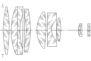
Since the II+ and III generation image intensifiers have a larger field of view and, in the long term, a very high resolution, reaching 64–82 lines/mm in the best foreign models [2, 3], it is necessary to modernize the NVG optics. For this purpose, a new Sirius-N lens was developed.
The lens operates in a wide spectral range of l = 540–900 nm, has a focal length of 173.6 mm, and a relative aperture of 1:1.7.
Its entrance pupil, with a diameter of 100 mm, coincides with the first surface of the lens.
The lens diagram is shown in Fig. 1.
The calculated values of the modulation transfer coefficients at a point on the axis at a spatial frequency of 50 mm-1 of the new Sirius-N lens are approximately 50% higher than those of the serial Helios-PA and Sirius-PA lenses.
This meets the increased requirements for the input lens of the NVG. The lens contains seven optical components, with the seventh component made in the form of a meniscus shifted by a given value relative to the main lens block.
This made it possible to increase the field of view of the lens to 2w = 80 due to high correction of the curvature of the field of view and aberrations of wide oblique beams.
The curvature of the field of view does not exceed 0.017 mm at the edge of the field of view.
This degree of aberration correction made it possible to obtain modulation transfer coefficients in the spectral range of 540 – 900 nm of at least:
— 0.75 for a point on the axis for a frequency of N = 30 mm-1;
— 0.58 for a point on the axis for a frequency of N = 60 mm-1;
— 0.55 for w = 40 for a frequency of N = 30 mm-1;
— 0.28 for w = 40 for a frequency of N = 60 mm-1.
Fig. 1. Diagram of the Sirius-N lens
High values of modulation transfer coefficients for the entire field of view provide higher image contrast of observed objects compared to serial lenses “Helios-PA” and Sirius-PA”.
The calculation results of the Sirius-N lens were modeled by synthesizing the image of the object (three-sleeper target) in the OPAL program, as well as by analyzing the image of the observed object obtained using the VOB program, located in a real terrain situation at various distances from the NVD.
The conducted computer modeling showed that due to the longer focal length (and, accordingly, a larger image scale), as well as due to the higher image contrast compared to serial lenses, the use of the Sirius-N lens allows increasing the recognition range of objects of observation in the NVD by 20%.
In order to achieve minimal dimensions and high image quality in upgraded NVDs of generations II+ and III, direct image transfer from the photocathode to the screen is used without 180° rotation.
In serial NVDs, inverter NVDs of the zero generation were used, in which the image was rotated by 180°. In this regard, in upgraded NVDs, an ocular system with image rotation is used instead of an eyepiece (Fig. 2).
The calculated wavelength of the ocular system is 546 nm with an achromatization range of 530-560 nm, a linear field of view of 18 mm, magnification of 0.5c, a numerical aperture in the space of objects of Sin U = 0.136, the exit pupil distance is 20 mm with its diameter of 7 mm.
This system has an additional image plane that can be used to input into the ocular system an image of the aiming scale, an LED range indicator and other service information.
In the TPN-3 sight, an image intensifier with a multi-alkaline photocathode was used for operation in the passive mode, and an image intensifier with an oxygen-silver-zinc photocathode was used for operation in the active mode.
To switch from one mode to another, the corresponding image intensifier was replaced, rotating in a drum with subsequent fixation.
In the modernized TPN-3 sight, instead of two image intensifier tubes, one image intensifier tube is used for operation in both modes. In this regard, a reversing optical system (Fig. 3) is installed in the vacated space in the rotating drum instead of the image intensifier tube. Together with the NVG lens and the eyepiece of the eyepiece system for the image intensifier tube, it forms a daytime orientation and observation channel.
Thus, when switching the drum positions, it is possible to ensure operation of either the night or daytime channels.
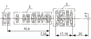
Fig. 2. Schematic diagram of the ocular system of the modernized NVD TPN-1, TPN-3, BPK-2: 1 – image intensifier; 2 – erecting system (transfer optics), 3 – eyepiece
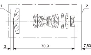
Fig. 3. Schematic diagram of the optical erecting system of the daytime channel of the modernized NVD TPN-3: 1 object plane; 2 – image plane
The proposed replacement of infrared (IR) spotlights on incandescent lamps and gas-discharge lamps with a unified small-sized spotlight based on an effective semiconductor laser, simultaneously with the modernization of the NVD, allows not only to increase the visibility range in the active operating mode, but also to increase the noise immunity and efficiency of the complex as a whole under operating conditions, especially since the production of xenon lamps at the Riga Electric Lamp Plant ceased in 1991.
The PL-1 floodlight [1] (photo 1) contains a single unit that functionally combines a laser emitter, a power supply unit, and a forming optical system, as well as a protective glass heating system.
The electrical connection between the object and the PL-1 floodlight is provided by a cable from the object kit. Using the mounting kit included with the floodlight, it is possible to replace lamp floodlights manufactured before
1991 with the PL-1 floodlight directly on the BTT objects without modifying the structural elements of the object.
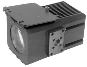
Photo 1. Laser spotlight PL-1
The spotlight forms a convenient rectangular radiation spot for the operator with a uniform distribution of radiation intensity, while lamp spotlights form a spot with a bell-shaped non-uniform distribution.
The advantages of the PL-1 floodlight also include smaller dimensions and weight (Table 2), which significantly reduces its vulnerability. The PL-1 floodlight is characterized by lower energy consumption and an increased service life compared to existing analogues.
This eliminates such defects of lamp floodlights as lamp explosion, failure to light, instability of brightness, destruction of the reflector and light filter during lamp explosion, etc.
It should also be noted that the PL-1 laser floodlight has good spectral matching with the photocathode of the II+ and III generation image intensifier tubes.
The issue of upgrading NVDs associated with the use of a laser illuminator deserves separate consideration, so here we have limited ourselves to only the main considerations that are essential from the point of view of upgrading.
Table 2. Comparative parameters of IR lamp and laser illuminators
| Illuminator type | IR lamp | IR lamp | IR laser |
| Illuminator model | L4 | OU-5 | PL -1 |
| Light intensity | 30×106 cd | 10×106 cd | 470 W/Wed |
| The working area of the spectrum, nm | 900 – 1200 | 900 – 1200 | 850 |
| Illumination angle, degrees. | 0.75 | 1.5 | 1.5х0.75 |
| Energy consumption, W | 400 | 300 | 50 (with heated protective glass), 20 (without heating) |
| Dimensions, mm | Ж300×280 (floodlight), 200х200х100 (power supply) |
Ж235х200 (floodlight) 100х100х150 (power supply) |
246х174х177 (floodlight with power supply) |
| Weight, kg | 20.5 | 12 | 7,0 |
Table 3 presents comparative parameters of serial and modernized NVDs (photos 2 – 4). The advantage of the latter is obvious.
Table 3. Comparative parameters of existing and modernized NVDs
| NVD model | TPN-1 | TPN-1 modernized, generation II+/III |
TPN-3 | TPN-3 modernization, generation II+/III |
BPK-2 | BPK-2 modernization, generation II+/III |
| Recognition range, m, in passive mode | not working | 1200/1300 | 500 | 1100/1200 | 600 | 1100/1200 |
| Recognition range, m, in active mode | 700 | 1300/1300 | 1300 | 1300/1300 | 900 | 1200/1200 |
| Field of view in passive mode, deg.: — day — night |
— 6 |
— 6015′ |
— 6040′ |
10 6040′ |
10 6 |
10 6040′ |
| Field of view angle in active mode, degrees. | 0.75 | 1.5×0.75 | 0.75 | 1.5×0.75 | 1.5 | 1.5×0.75 |
| Magnification, times: — day — night |
— 5.5 |
— 6.4 |
— 5.5 |
4.2 5.5 |
6 5.5 |
6 5.85 |
| IR illuminator | L4 | PL-1 | L4 | PL-1 | OU-5 | PL-1 |

Photo 2. Upgraded TPN-1 night vision device and its position on the tank
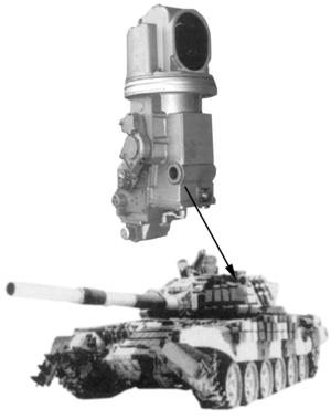
Photo 3. The upgraded TPN-3 NVG and its position on the tank
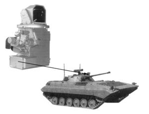
Photo 4. The upgraded BPK-2 NVG and its position on the BMP-2
The presence of an additional image plane in the NVG ocular system allows for the next step in modernization – introducing a television (TV) channel into the NVG.
To do this, remove the eyepiece from the eyepiece system and replace it with a CCD-based TV camera.
The image plane of the eyepiece system coincides with the light-sensitive element of the TV camera (Fig. 4).
The latter can be used, for example, the WAT-902H model from Watec, Japan (photo 5) [4].
This 1/2-inch TV camera has a sensitivity of 3×10⁻⁴ lux, a resolution of 570 TV lines, a signal-to-noise ratio of 50 dB, a supply current of 170 mA at a DC voltage of 12 V, a weight of 90 g, and dimensions of 34x34x58 mm.
To view TV images, a liquid crystal TV monitor KB Display, specially designed for armored vehicles, can be used [5]. The MDC 066 TV monitor (photo 6) has a screen size of 18.4 x 13.8 cm, a screen brightness of up to 800 cd, a resolution of 600 x 600 pixels, a power consumption of 40 W when powered from the on-board network = 27 V, a weight of 2.5 kg, dimensions of 196 x 192 x 90 mm, and a range of maximum operating temperatures of (-60) – (85) 0 C. [5]. Due to the loss of image quality in the TV channel, the viewing range of the NVD will be reduced by 20%.
However, this disadvantage is offset by many advantages of TV NVD:
— duplication of the image to the gunner and commander of the BTT object;
— the possibility of remote transmission of the image;
— introduction of a sighting scale, as well as any alphanumeric and symbolic information into the electronic channel of the TV camera;
— additional suppression of light interference in the TV channel;
— automatic correction of image quality in real time;
— adjustment of image contrast and brightness.
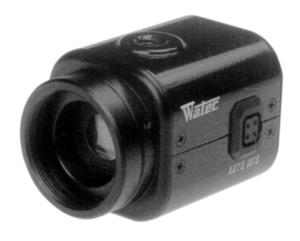
Photo 5. TV camera WAT-902H
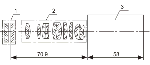
Fig. 4. An example of optical coupling of the WAT-902H TV camera with an image intensifier: 1 – image intensifier, 2 – erecting system from the eyepiece system, 3 – TV camera
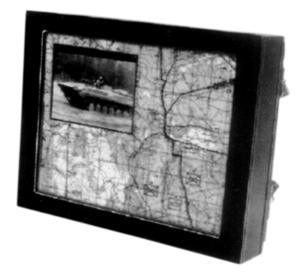
Photo 6. TV monitor MDC 066
The next step of modernization is the introduction of the active-pulse (AP) mode of operation of the NVD.
The essence of the AI mode is as follows [6]. The object of observation is illuminated by short light pulses, the duration of which is significantly less than the time it takes for light to travel to the object and back.
In this case, the object is observed in a night vision device equipped with a fast-acting shutter that opens in time with the sending of light pulses for a certain time.
In the case where the time delay between the moment of pulse emission and the moment of shutter opening is equal to twice the time required for light to travel the distance to the object and back, the observer will see only the object itself and the area of space immediately surrounding it.
The depth of this space is determined by both the time the shutter is open and the duration of the light pulse.
The high-speed shutter is an image intensifier tube of generations II+ and III, and the source of short light pulses is a pulsed laser illuminator PL-1. Pulse control (strobing of the image intensifier tube) and synchronized pulsed operation of the laser illuminator is performed using a special strobing unit.
Advantages of the AI mode:
- Increased contrast in the image of the observed object, and therefore the range of the NVD (in the NVDs under consideration up to 1800 – 2000 m) due to:
- cutting off backscattered radiation by delay, which in conventional active night vision devices is superimposed on the image of the observed object and reduces the contrast in its image even in normal or slightly degraded atmospheric transparency; at the same time, the AI mode is most effective in those hazes, fogs, etc., where thermal imaging devices are least effective;
- attenuation, equal to the duty cycle of the device, of radiation scattered in the atmosphere, determined by the level of natural illumination;
- cutting off the background image.
- The introduction of the AI mode allows measuring the range to the observed object: since the image of the observed object appears only after a certain delay corresponding to the range to the object, the range to the object can be measured by the delay with an accuracy of ± 10 m and higher; unlike conventional laser rangefinders, this eliminates the possibility of giving a false range value due to the rangefinder's reaction to random objects located between the target and the NVD; since in the AI NVD these false signals are cut off by the delay.
- The introduction of the AI mode allows increasing the noise immunity of the NVD by 1000 times due to the suppression of light interference in a number of times equal to the duty cycle of the NVD, as well as due to spectral selection associated with the installation of a narrow-band filter with a passband corresponding to the spectrum of the laser illuminator in front of the photocathode of the image intensifier.
The AI mode has two disadvantages:
— unmasking associated with the active operating mode;
— the practical impossibility of searching in the AI mode, since the search must be carried out not only by field, but also by a narrow strobe in depth.
In this regard, at the standardized level of EHO, the search should be carried out in passive mode. The detection range of objects in this mode is usually 1.3 — 1.5 times greater than the recognition range.
Therefore, when an object is detected in passive mode, it is recognized and the range to it is measured in the AI mode; at a reduced level of EHO, the search is carried out in active-continuous mode.
The PL-1 floodlight operates in the pulse mode required for the implementation of the AI NVD (its operating frequency is 5.2 kHz with a backlight pulse duration of 130 ns); it requires minor modification to ensure synchronization with the NVD.
The strobe unit, time interval meter, and range indicator can be borrowed from the Sozh device [1]; only its structural adaptation to the NVD will be required.
It is necessary to dwell in particular on the issue of observation of objects during mutual movement in depth of the object of observation and the object of the armored vehicle — the carrier of the AI NVG.
During this movement, the operator must continuously change the delay so that the image of the object of observation does not go beyond the strobe. However, this will distract the operator from his direct functions.
Therefore, two options for solving this problem are possible.
- A constant delay is introduced, cutting off the near part of the space in front of the AI NVD, which makes the greatest contribution to the amount of backscattering of the illumination radiation and, accordingly, to the reduction of the image contrast; this is the simplest solution, but it will lead to the impossibility of measuring the distance to the object of observation and to a decrease in the degree of protection from light interference.
- A photodetector is introduced into the eyepiece part of the AI NVG (or in front of the TV camera, if the AI NVG contains a TV channel); simultaneously, the strobe unit, in addition to the main strobe, forms two auxiliary strobes before and after the main strobe, respectively, with a frequency different from the frequency of the main strobe and negligibly small, so that the operator does not react to images within these strobes [7]. Let us assume that one of the auxiliary strobes has a frequency of 10 Hz, and the other — 15 Hz. If the observed object goes beyond the main strobe and falls within the strobe with a frequency of 10 Hz, then an electrical signal with this frequency will arise in the photodetector circuit. In this case, a difference signal will arise in the comparator of the strobe unit, which will change the delay until the signal with a frequency of 10 Hz disappears, i.e. until the object is again within the main strobe. When the object enters the limits of another auxiliary strobe, a signal with a frequency of 15 Hz will appear. Then a difference signal will appear, changing the delay until the signal with a frequency of 15 Hz disappears, i.e. until the object is again within the limits of the main strobe. This will be the automatic correction of the delay, ensuring constant visibility of the observed object during its relative movement with the BTT object.
Further prospects are associated with the use of interchangeable generations III+ and IV image intensifiers instead of generations II+ and III [3].
They implement both a further increase in the sensitivity of the photocathode and a shift in the long-wave sensitivity limit to the spectrum region of 1.0 – 1.55 μm.
At the same time, the laser spotlight should replace the 0.85 µm semiconductor laser emitter with a wavelength of 1.55 µm.
This will dramatically increase the contrast in the image, improve visibility under unfavorable conditions, including in tactical smoke [3].
At the same time, radiation at a wavelength of 1.55 µm is invisible to the eye and safe for it.
Thus, there are many prospects for further modernization of the NVD.
Literature
1. Volkov V.G. Night vision devices for armored vehicles./Special equipment, 2004, No.5, p. 2 13; No.6, pp. 2 – 10.
2. Volkov V.G. Electron-optical converters. Review No. 5592, Moscow: NTC Informtekhnika, 2002, 143 p.
3. Volkov V.G. Night vision devices of new generations./Special equipment, 2001, No.5, pp. 2 – 8.
4. Volkov V.G. Ultra-high-sensitivity television systems./Special equipment, 2002, 4, pp. 2 – 11.
5. Catalogue of KB “Display”. Development and production of products for operation in harsh operating conditions of flat panel video monitors, cathode ray tube video monitors, panel computers. Belarus, Vitebsk, 2004.
6. Volkov V.G. Active-pulse night vision devices./Special equipment, 2003, No. 2, pp. 2 – 14.
7. Volkov V.G. Active-pulse night vision devices for simultaneous observation of close, distant, and moving objects. Defense complex – scientific and technical progress of Russia, 2001, No. 1, pp. 89 – 95.
