Information protection in the optical frequency range.
The need for effective communication systems is caused by the growing costs of replacing and modifying equipment and the increasing demand for all means of information protection, especially in television, radio, telephony and computing.
In the last decade, new types of communication have appeared, such as dispatch television, video telephony, and systems for transmitting video information.
Most of these systems are limited by one important factor — the width of the information band.
Wired and coaxial communication lines provide information transmission at frequencies extending up to 10^9 Hz.
The use of channel compression methods and coding techniques increases the bandwidth of these systems to a higher level of information transmission speed on channels.
When using light modulated with a frequency of about 10^10 Hz to transmit information, it is possible to increase the bandwidth by several orders of magnitude.
The first works on the propagation of light in various media were related to liquid light guides; in this case, the possibility of using the direction of light in a stream of water flowing out of a vessel was demonstrated (Tyndall's experiments, 1880).
In 1910, Hondras and Debye reported on the theoretical development of the transmission of light signals through a dielectric waveguide, and ten years later, Schriever conducted the first experiments on the transmission of light through a dielectric rod surrounded by air.
In 1954, Hell, Hopkins, and Conany proposed various applications of a dielectric waveguide made of glass fiber, having two layers, one of which served as a reflective cladding.
Glass fiber suitable for use in communication systems was developed in the period 1966-1973.
Since 1975, both in our country and abroad, the development and implementation of fiber-optic information transmission systems (FOIS) began. The most important characteristics of FOIS, which determine their advantage over metal cables, are:
1) weak signal attenuation and its lower dependence on the wavelength of the transmitted optical information signal. mode distribution and cable temperature;
2) minor signal distortion and its weak dependence on the spectral width, mode distribution, amplitude and wavelength of the transmitted optical information signal, the length of the fiber optic cable and the ambient temperature;
3) low radiation losses and their slight dependence on the bending radius and temperature of the fiber optic cable;
4) more acceptable physical parameters — weight, size, total volume;
5) ease of installation, splicing and input of radiation into the fiber optic cable;
6) high resistance to external influences — moisture resistance, heat resistance, resistance to chemical corrosion and stress corrosion, mechanical loads.
Despite the above advantages, VOSPI also have disadvantages, in particular, information leakage is possible due to side electromagnetic radiation and interference (SEMI) in both the radio frequency and optical ranges.
|
|
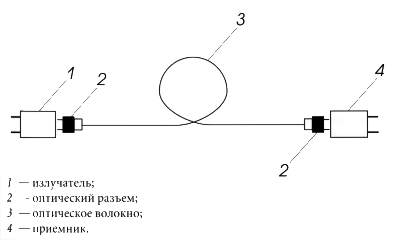
Possible information leakage channels in the radio frequency range have been studied in detail and are known. Since the early 80s, both our and foreign scientists, along with the development of VOSPI, have been working to identify possible information leakage channels in the optical frequency range. To analyze possible information leakage channels, let us consider the simplest VOSPI model (Fig. 1). |
Two types of semiconductor devices can be used as emitters for VOSPI.
The simplest type of device, a light-emitting diode, has a wide radiation pattern and is therefore suitable for use with multimode fiber optics with a large core diameter.
More complex devices, such as semiconductor lasers, emit much better collimated light beams and therefore allow a higher-power signal (10 to 100 times) to be introduced into multimode fiber optics, as well as effectively introduce a signal into single-mode fiber optics with a small core diameter.
Light-emitting diodes are quite suitable for use in information channels and in communication systems with low or moderate bandwidth.
Information leakage at the emitter is possible:
• due to mismatch of the geometric dimensions of the window (microlens) of the light-emitting diode or semiconductor laser and the end (aperture) of the fiber optic light guide;
• due to «transparency windows» around the contacts on the substrate, to which the transmitted information signal is supplied in the radio frequency range.
The numerical aperture of a fiber optic light guide is determined by the expression  where nс is the refractive index of the fiber optic light guide core;
no is the refractive index of the cladding.
Photodiodes are usually used as a receiver in a VOSPI. Leakage at the receiver in the optical frequency range is possible:
‘ due to the mismatch of the geometric dimensions of the window (microlens) of the photodiode and the end of the fiber optic light guide;
• due to the «transparency windows» around the contacts on the substrate, to which the received information signal in the radio frequency range is supplied.
To eliminate information leakage in the optical frequency range, the emitter and receiver must have a design that is physically an absolutely «black body». As a rule, losses in optical connectors are 2.5-4.5 dB.
Of greatest interest is the emission of information from optical fiber. At present, all fiber optic light guides produced by industry can be divided into three types:
• multimode fiber optic light guide;
• few-mode fiber optic light guide;
• single-mode fiber optic light guide.
In addition, fiber optic light guides can have a step refractive index and a gradient refractive index.
Absolutely all optical fibers have attenuation. Light attenuation in an optical fiber is caused by absorption and scattering in the material, scattering associated with the optical fiber structure, and radiation losses.
Scattering associated with the optical fiber structure is caused mostly by geometric inhomogeneities of the core-cladding interface.
By carefully controlling the manufacturing process, it is possible to maintain the level of scattering losses of this type below 1 dB/km. Radiation losses are caused by bends in the fiber optic cable and can be significant at small radii of curvature.
Radiation from a fiber optic cable reaches especially high values if the optical cable is made using fibers without a soft, shock-absorbing plastic sheath.
Light scattering due to fluctuations in the density of the optical fiber material is determined by the expression  where T is the transition temperature at which thermal fluctuations are “frozen in the glass”;
B is the isothermal compressibility;
λ is the wavelength of the transmitted optical signal.
For fused silica, which has T~1700 K, the value of as at a wavelength of 830 nm is approximately 1-6 dB/km.
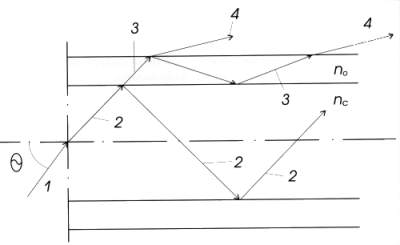
For a more visual representation, let us consider the structure of the field of the transmitted information optical signal through a multimode fiber with a step refractive index (Fig. 2).
|
|
0 — angle of optical signal input into fiber; nc — refractive index of optical fiber core; no — refractive index of optical fiber cladding; 1 — trajectory of beam (mode) input into fiber; 2 — trajectory of beam (mode) of transmitted optical information signal along fiber core; 3 — the trajectory of the beam (mode) transmitted along the fiber cladding; 4 — the trajectory of the leaky beam (mode). |
From the point of view of information leakage, the most dangerous are the «cladding» and «leaking» modes, since, having access to this type of optical fiber, using highly sensitive photodetectors (microlenses or a special optical fiber optically matched to the main one using a specially selected emission liquid can be used as an optical lens), it is possible to receive the transmitted optical signal.
If there are structural defects in the optical cable, stresses applied perpendicular to the axis of the optical fiber can cause it to bend with a small radius of curvature.
Axial stresses can also lead to bends if there are structural inhomogeneities, to the elongation of the light guide and the growth of microcracks.
The influence of these phenomena on the attenuation of the optical signal in the fiber must be taken into account when developing the design of the optical cable and selecting the type of fiber.
The emission of the optical signal caused by the bending of the fiber can significantly increase the optical losses of the fiber in the cable.
In most cases, bends with a curvature radius of  where r is the radius of the fiber core, NA is the numerical aperture of the fiber, lead to very large spurious radiation at the bend.
Therefore, the bending radius of the optical fiber in the cable must be significantly larger than r .
For large radii of curvature R, the spurious radiation of the optical signal at the bend will decrease exponentially in accordance with exp(-R/Rmin).
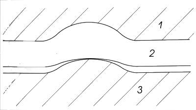
Stress on the bumps can cause the fiber to bend and increase spurious emission. Stress can also cause microcracks to enlarge and cause a change in the refractive index, which in turn can also cause spurious emission from the fiber to increase.
|
|
In Fig. 3 shows an optical fiber subjected to transverse stresses on a bulge in the cable, where: I is the filler material in the optical cable; 2 is the fiber optic cable; 3 is the central element of the optical cable. |
The dependence of the spurious radiation due to the transverse stress caused by the bending of the light guide OS on the core radius r and the relative difference in refractive indices A is expressed by the following formula:  b is the diameter of the light guide;
nc is the refractive index of the light guide;
nоб is the refractive index of the cladding;
h is the root-mean-square value of the convexity;
p — the number of convexities per unit length;
Eob — Young's modulus of the cladding material;
Ec — Young's modulus of the fiber core material.
Usually, the operating mode of a fiber is characterized by a generalized parameter that includes the core radius, wavelength, and refractive indices of the core and cladding, which is called the normalized frequency: 
At sufficiently high frequencies (large V value), almost all the field energy is concentrated inside the fiber core, and as the frequency decreases, the field is redistributed and passes into the surrounding space.
The frequency f0, at which the field is radiated into the surrounding space in the range f >= f0, is called the cutoff frequency. The further f is from it, the faster the energy is «emitted» from the fiber.
It should also be noted that the «leaky» modes (Fig. 2) are in turn divided into weakly attenuated and rapidly attenuated modes.
Unlike rapidly attenuated modes of radiation, which are almost completely attenuated on a three-meter section of optical fiber, weakly attenuated modes attenuate relatively slowly and have a noticeable effect on the measurements of spurious radiation at measured cable section lengths of up to hundreds of meters.
For example, in gradient multimode fibers with a parabolic profile, about 25% of the propagated energy can be contained in weakly leaky modes.
All of the above was considered in relation to a fiber optic light guide.
If we consider an optical cable consisting of several optical fibers through which confidential information with different classifications is transmitted, then another information leakage channel arises due to transient attenuation caused by leaky modes.
Access to the optical fibers of the cable to improve the reception of information in the optical frequency range is possible due to:
• mechanical action;
• chemical exposure;
• exposure to hard beam radiation.
In conclusion, it should be noted that when constructing a FOSS for transmitting confidential information, it is necessary to analyze in detail the operating conditions, information classification, and select the type of optical cable that allows information to be protected from possible leakage due to spurious radiation in the optical frequency range.
In addition to structural means of information protection, active protection can also be used, in particular noise suppression in the optical range and quantum cryptography.
Literature
1. Snyder A. Love J. Theory of optical waveguides. Moscow: Radio and Communications, 1987.
2. Unger. H-G. Planar and fiber optical waveguides. M.: Mir, 1989.
3. Grodnev I. and Shvartsman V. O. Theory of guiding communication systems. M.: Svyaz, 1978.
4. Unger G. G. Optical communication. M.: Svyaz, 1977.
E. Kozanis A., Fleuret J., Metre G., Russo M. Optics and communication. M.: Mir, 1984.


Добавить комментарий