Все про видеонаблюдение
Все про умный дом
Все о пожарной безопасности
Сейчас читают
 Как ускорить и смотреть ютуб без тормозов и замедленияЕсли Вы на этой странице, то Вам, скорее всего, […]
 10 лучших прогрессивных языков программирования для разработки мобильных приложенийЗнаете ли вы, что мобильные приложения — это не только […]
 6 важных особенностей, которые следует учитывать при строительстве нового домаСтроительство нового дома – это уникальная возможность […]
Гороскоп на Сегодня
Head-mounted night vision devices.
VOLKOV Viktor Genrikhovich,
Candidate of Technical Sciences, Associate Professor
Efficient night vision devices (NVD) are required for special operations [1].
They provide observation at dusk, at night, and in some cases also in low atmospheric transparency (haze, fog, rain, snowfall, etc.).
At the same time, situations often arise when the operator's hands must be free (for example, during rescue operations, anti-terrorist operations, during landing, when driving is necessary vehicles, etc.).
To meet this condition, the NVD must be mounted on the operator's head. In this case, head-mounted NVDs can be made in the form of:
- night vision goggles;
- low-level television system (LLTS);
- thermal imaging device;
- helmet-mounted combined device.
Night vision goggles as head-mounted NVDs historically appeared earliest of all.
In this case, a distinction is made between binocular and pseudo-binocular night vision goggles [1].
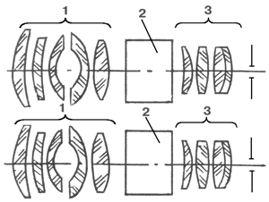
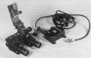
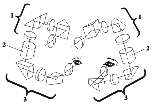
Binocular goggles consist of two identical night channels for the right and left eyes of the operator (photo 1). Each channel consists of an objective 1, an electron-optical converter (EOC) 2 [2] and an eyepiece 3 (Fig. 1).
The goggles provide smooth adjustment of the distance between the pupils of the eyes (the eye base) within 52 — 72 mm.
In some models, such adjustment is absent, and the possibility of observation by operators with different eye bases is ensured by large diameters of the exit pupils of the eyepieces, amounting to 12 — 13 mm [3], while the maximum diameter of the pupil of the eye does not exceed 8 mm.
In glasses of any type, dioptric focusing of the eyepieces is provided within ±5 diopters, sometimes (+2) — (-6) diopters, as well as refocusing of the lenses from the final distance of best vision (0.25 m) to infinity.
Such refocusing is necessary for observing both distant and nearby objects (e.g., a terrain map, repair tools, instrument panel).
The main parameters of typical binocular night vision goggles are given in Table 1.
They are most often made on the basis of image intensifier tubes of generations II+, II++, III, and in recent years in the USA – IV [4, 5].
The glasses are powered by a standard primary power source: two AA batteries with a voltage of 2.5 — 3 V DC, in some cases from one AA battery with a voltage of 1.5 V.
Depending on their capacity, the batteries allow continuous operation of the glasses from 8 to 40 hours.
The glasses are attached to a face mask, which in turn is mounted on the head using a strap headband with adjustable dimensions.
Binocular glasses provide a stereoscopic effect, which is convenient for driving.
In this regard, it is necessary to dwell on the variety of such devices — night vision goggles for the pilot [1, 3, 6 — 8] (photo 2a).
A distinctive feature of such goggles is that they are attached not to the face mask, but to the pilot's helmet (photo 2b).
The design of the goggles provides for the adjustment of their position in relation to the operator's face within all six degrees of freedom.
To ensure ejection, the design of the goggles attachment unit provides for the possibility of their quick release.
In addition, it is possible to fold the glasses from the working position to the non-working position.
The pilot's glasses have both an autonomous built-in primary power source, like conventional night vision glasses, and power from the aircraft's on-board network.
To ensure mass balancing, a counterweight is attached to the rear surface of the pilot's helmet.
A pilot wearing night vision goggles must observe both the space behind the cockpit and the instrument panel.
However, its illuminated indicators create an excessive light load for the goggles.
Therefore, special interference filters “minus blue” are placed on the lenses of the goggles, cutting off part of the visible light.
This, combined with the organization of optimal lighting in the cockpit spectrum, allows observation through the goggles of both the space behind the cockpit and the instrument panel.
However, to observe this space, the lenses of the glasses must be focused to infinity, and to observe the instrument panel — to a finite distance.
Since refocusing of the lenses during flight control is impossible, the glasses have a large eyepiece exit pupil distance — over 20 mm.
This allows the pilot, squinting, to observe the instrument panel, bypassing the night channels.
Photo 1. External appearance of typical binocular night vision goggles

Fig. 1. Optical diagram of binocular night vision goggles
a)

b)
Photo 2. The appearance of typical binocular aviation night vision goggles (a), the same on the pilot's helmet (b).
Table 1. The main parameters of typical binocular night vision goggles
This is not very convenient, so the company GEC Avionics (Great Britain) developed Cats Eyes goggles with a prism ocular system [9].
The appearance of the goggles is shown in photo 3, and their optical diagram is in Fig. 2, where 1 is the objective, 2 is the image intensifier, 3prism eyepiece system.
In it, the prism has a curved hypotenuse surface with a dichroic coating that reflects in the spectrum area of the image intensifier screen (yellow-green spectrum range) and transmits visible light from the instrument panel and the interior of the cabin.
As a result, the pilot sees both the space behind the cabin and the instrument panel at the same time.
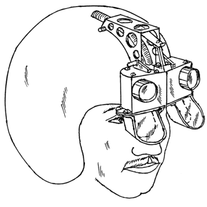
A variety of such glasses is the model from Marconi Avionics Ltd. (Great Britain).
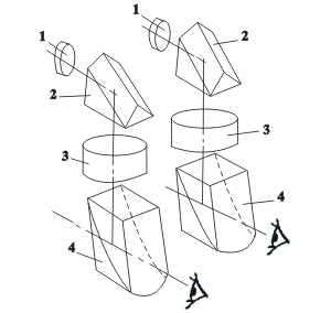
Their appearance is shown in Fig. 3a, and the optical diagram is shown in Fig. 3b [10].
Such simultaneous observation of night and visual images is called “see-through vision”. The specified glasses also have small longitudinal dimensions.
This allows them to be classified as so-called “low profile” night vision glasses (see below).
The company has also developed glasses for a pilot, the diagram of which is shown in Fig. 4.
Mirror 3 with a dichroic coating provides “see-through vision” [11].
To increase the plasticity of the glasses and, accordingly, to increase their stereoscopic vision range, the ITT company (USA) developed the Merlin glasses [12].
The main parameters of typical aviation night vision glasses are given in Table 2.
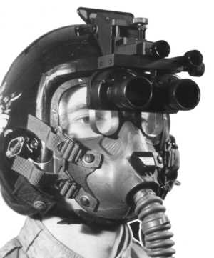
Photo 3. Appearance of the Cats Eyes night vision glasses
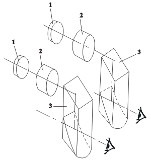
Fig. 2. Optical diagram of Cats Eyes night vision goggles
a)
b)
Fig. 3. External appearance of night vision goggles [9] (a) and their optical scheme (b), where
1 – objective, 2 – roof prism, 3 – image intensifier, 4 – prism eyepiece system
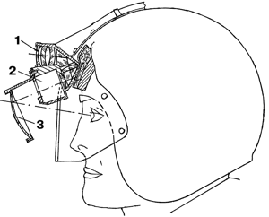
Fig. 4. Schematic diagram of aviation night vision goggles by Marconi Avionics Ltd., where
1 – objective with prisms, 2 – image intensifier, 3 – eyepiece dichroic mirror.
Table 2. Main parameters of aviation night vision goggles.
A common disadvantage of pilot glasses is the limited angle of their field of view.
To increase it in the horizontal direction, some binocular night vision glasses practiced moving the optical axes of individual channels apart [11].
In this case, the total angle of the field of view along the horizon reached 400 with the angle of the field of view of individual channels being 250.
However, such glasses cause rapid eye fatigue.
In addition, many people do not have sufficient convergence of the eyes — the ability to move their optical axes apart.
To radically increase the angle of view, the ITT company (USA) developed the so-called panoramic night vision goggles PNVG (Panoramic Night Vision Goggle) [13 – 18].
The PNVG-1 version of the goggles is based on four specially developed by the company image intensifier tubes without image rotation with a photocathode diameter of 16 mm and a weight of 22 g [17].
The goggles have a field of view angle of 1000 horizontally and 400 vertically.
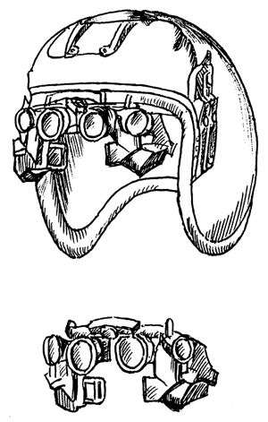
Fig. 5a shows the appearance of the PNVG-1 goggles, Fig. 5b shows the same goggles mounted on the pilot's helmet in comparison with traditional goggles (shown in dotted lines).
Fig. 5c shows the optical diagram of the two central night channels of the goggles [18], which is the basis of the AN/PVS-21 low-profile goggles [14].
ITT also developed the PNVG-2 model [13 – 18].
It is extremely simple, although it is not low-profile.
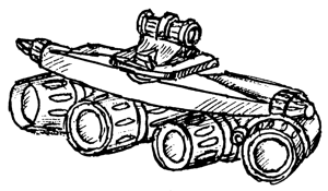
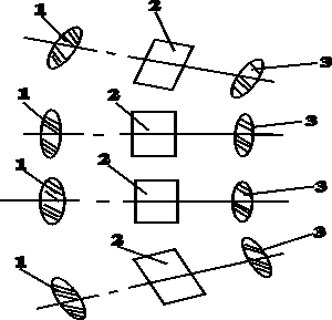
The device (Fig. 6a) consists of four night channels according to the diagram in Fig. 6b, c, where 1 is the objective, 2 is the image intensifier, 3 is the eyepiece.
The optical axes of the two central channels are mutually parallel, and the axes of the two lateral channels are set apart by an angle of 100 each.
These glasses use an image intensifier from the same company, but with image rotation.
With a photocathode diameter of 16 mm, the mass of the image intensifier is 51 g.
The total mass of the device reaches 750 g.
In this case, binocular vision is maintained within a field of view angle of 300.
The right and left eyes separately cover a field of view angle of 400.
To observe the peripheral areas of the visual field, the operator moves the pupils of the eyes to the right or left, respectively. The field of vision is observed without breaks.
Its appearance is shown in Fig. 7.
It shows the field of vision of a miniature thermal imaging channel combined with glasses [15].
This channel provides an enlarged image of the object.
a)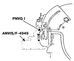
б)
в)
Fig. 5. External appearance of PNVG 1 night vision goggles (a), their helmet-mounted location (b) in comparison with traditional ANVIS (F 4949) goggles (dotted line), optical diagram of PNVG 1 goggles for two night channels (c), where 1 is the objective, 2 is the image intensifier, 3 is the ocular system
a)
a)

a)
Fig. 6. Appearance of PNVG 2 night vision goggles (a) and options for their optical designs (b, c)
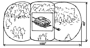
Fig. 7. External view of the field of view of the PNVG night vision goggles; in the center is an additional image from the built-in small-sized thermal imaging channel
The desire to provide end-to-end vision” also led to the creation of so-called “holographic” night vision goggles.
Their name is not associated with the method of creating an image, but with the same technology for making mirrors as for holographic optical elements.
The OIP company (Belgium) has developed binocular glasses HNV-3D [6, 19] (photo 4), their optical scheme is given in Fig. 8, where 1 is the objective, 2 is the image intensifier, 3 is the “holographic mirror”, 4 is the ocular system.
The central part of the glasses is occupied by the night image with a field of view angle of 400, and the peripheral part is occupied by the daytime image with a field of view angle of up to 1000.
These glasses are low-profile. The dichroic coating of the mirror 4 reflects in the glow spectrum of the image intensifier tube screen and transmits in the rest of the visible spectrum.
The operator simultaneously sees both the image of the scene through the night channels of the glasses and the image of the same scene, bypassing the image intensifier tube.
This allows continuous observation under the influence of light interference, when the night channel becomes inoperative.
“End-to-end vision” is also provided by the AN/AVS-502 night vision goggles [31] (photo 5).
Their night field of view is 400 with a total field of view angle of 100×900.
The device can be combined with the pilot’s head-mounted display. Thanks to this, an image of the thermal imaging channel or service information can be introduced into the field of view.
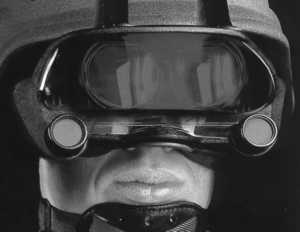
Photo 4. External appearance of the “holographic” night vision goggles HNV-3D
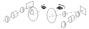
Fig. 8. Optical diagram of the “holographic” night vision goggles HNV-3D
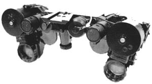
Photo 5. External appearance of the night vision goggles AN/AVS-502
Night vision goggles can also be supplemented with a compact communication system based on a semiconductor laser [20], developed by Philips (Netherlands) (photo 6).
The transmitter built into the goggles has a lens with a variable focal length to ensure that the laser operates with both a narrow beam (for communication) and a wide beam (for illumination).
The communication range is 1 — 2 km with a supply voltage of 9 V and a continuous operation time of the communication system of 4 hours.
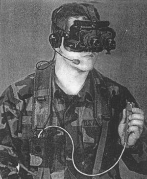
Photo 6. Appearance of night vision goggles with built-in communication system
The disadvantages of binocular goggles are their relatively large weight and cost. The latter is determined mainly by the image intensifier.
In this regard, pseudo-binocular night vision goggles have become widespread [6].
They contain one objective lens, one image intensifier, the image from the screen of which is divided into two eyes using the ocular system (photo 7, fig. 9).
Table 3 presents the main parameters of typical pseudo-binocular night vision goggles.
Their low weight and the presence of one objective lens make it easy to transform the goggles into night binoculars using a replaceable Galilean telescopic lens attachment (photo 8).
Thanks to the attachment, the magnification of the device increases from 1x to 3 – 5x depending on the magnification of the attachment [6]. Accordingly, the range of the device increases by 1.5 – 2 times.
However, its field of view angle decreases by as many times as the magnification has increased.
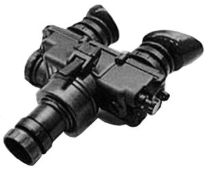
Photo 7. Appearance of typical pseudo-binocular night vision goggles
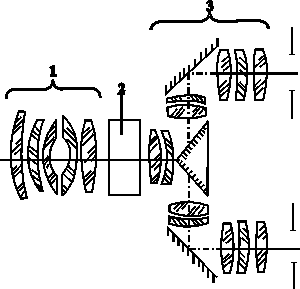
Fig. 9. Optical diagram of pseudo-binocular night vision goggles, where 1 is the objective, 2 is the image intensifier, 3 is the ocular system
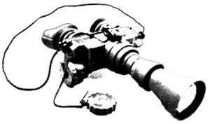
Photo 8. External appearance of pseudo-binocular night vision goggles with a telescopic attachment
Table 3. Main parameters of typical pseudo-binocular night vision goggles
A common drawback of the most common traditional glasses is their significant longitudinal dimensions.
They cause a large overturning moment.
It creates a load on the operator's neck and facial muscles, causing fatigue.
Therefore, the efforts of developers are aimed at creating low-profile («flat») night vision glasses with minimal longitudinal dimensions.
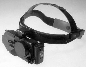
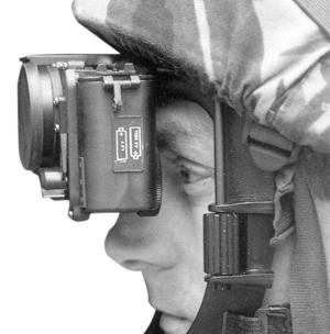
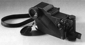
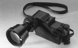
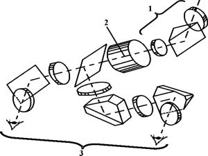
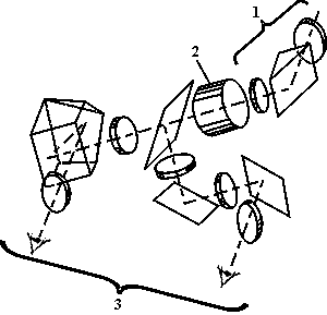
A typical example is the GN-2 device by Simrad (Norway) (photo 9, fig. 10) [21, 22], the Lucie glasses by ANGENIEUX (France) [23, 24] (photo 10, fig. 11), and the Clara glasses [25] (photo 11) by Sfim (France) [25].
The design of the low-profile glasses NV/G-14 Belomo (Republic of Belarus) [26] is based on the same principle as the GN-2 glasses.
The main parameters of the low-profile glasses are given in Table 4.
The distance from the first surface of the glasses to the pupil of the eye does not exceed 80 mm in such devices, while for traditional glasses this dimension ranges from 135 to 200 mm.
The AN/GVS-21 low-profile glasses [15] have been developed in the USA.
Systems Research Laboratories (USA) has also developed the Model 2777 low-profile glasses [27] (Fig. 12).
These glasses are made according to the optical scheme of Fig. 5c based on a third-generation image intensifier tube, and have a field of view of 400. The glasses [28], which are built into the pilot's head-mounted display, are made according to the same scheme.
a)
b)
Photo 9. Appearance of night vision goggles GN-2 (a) , their location on the head (b)
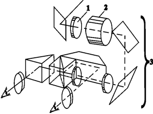
Fig. 10. Optical diagram of the GN-2 night vision goggles, where 1 is the objective, 2 is the image intensifier, 3 is the eyepiece system
a)
b)
Photo 10. External appearance of the Lucie night vision goggles (a), the same with a telescopic attachment (b)
a)
b)
Fig. 11. Variants of optical schemes of night vision goggles Lucie (a, b), where 1 is the lens, 2 is the image intensifier, 3 is the ocular system
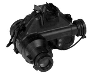
Photo 11. External appearance of night vision goggles Clara
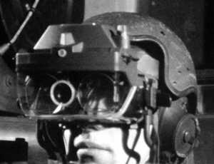
Fig. 12. External appearance of the Model M 2777 night vision goggles
Table 4. Main parameters of low-profile night vision goggles
The OIP company (Belgium) has also developed pseudo-binocular “holographic glasses HNV-1 [29] (photo 12). The operating principle of the device is similar to the HNV-3 model.
Historically, the HNV-1 device appeared earlier than the HNV-3.

Photo 12. External appearance of the “holographic” night vision goggles HNV-1
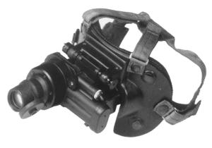
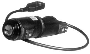
Night vision goggles can be used in combination with a laser designator mounted on a weapon and creating a “point” image of the illumination spot on the target [30] (photo 13).
This sighting system allows firing from any weapon position and on the move.
a)
b)
Photo 13. Night sighting system: TN2-1 night vision goggles (a) and PS1 laser designator (b)
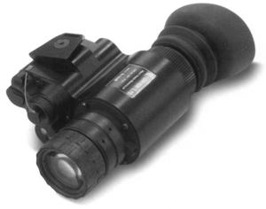
A type of night vision goggles are night head-mounted monoculars [1, 6] (photo 14).
In essence, this is one night channel of binocular goggles with an autonomous power supply and a characteristic design for attachment to a face mask or headband.
The unified design of the monoculars allows them to be used as small-sized hand-held night observation devices (“pocketscopes”), to be coupled with photo and video cameras for night shooting, and to be used as night sights for light small arms [6].
The main parameters of typical head-mounted monoculars are given in Table. 5.
a)

b)
Photo 14. Appearance of a typical night head-mounted monocular (a) and its working position (b)
Table 5. Basic parameters of typical head-mounted monoculars
All night vision goggles and night head-mounted monoculars have a built-in IR LED operating at a wavelength of 0.82 – 0.85 µm with an illumination angle of 400 and designed to illuminate nearby objects for the purpose of carrying out covert repair work, reading maps, etc.
Advances in the field of creating highly sensitive TV cameras based on CCD matrices have led to the development of head-mounted NTVS.
They can be of two types:
- the TV camera itself is located on the individual weapon, and on the operator's head there is only a small-sized TV monitor with ocular optics, attached to the headband [32, 41];
- the entire NTVS is mounted on the operator's head [33, 34].
An example of the first system is the Argus-21 device [32, 41].
The detection range of a full-length human figure on a starry night is 350 m with a field of view of 8–100, supply voltage = 12 V, TV camera dimensions of 40×160 mm, its weight is 1.5 kg, and the TV display is 210x195x110 mm and 0.5 kg, respectively.
Examples of the second system include the IHDTV (Intensified High Definition Television) from Bell Aerospace on Technology Corp. (USA) [33] and the Kamera-Brille Type 88505 TV EMO-Electronik (Germany) [34].
The IHDTV device consists of a lens, a fourth-generation image intensifier [5], mated with a TV camera based on a CCD matrix.
The weight of the device is less than 900 g, the volume is less than 0.5 l.
The device contains a strobe unit operating with a strobe pulse duration from 100 ns to 16.6 ms.
It provides suppression of light interference. The Kamera-Brille Typ 88505 device contains a TV camera, a TV monitor and two eyepieces focused on its screen.
The device has a field of view of 400, a weight of 500 g, a focusing range of 0.1 m — infinity, eye base adjustment limits of 60 — 72 mm, eyepiece diopter adjustment limits of ±5 diopters, and is powered by a separate 12 V DC battery, which provides 3 — 4 hours of continuous operation of the device.
The creation of effective focal-plane microbolometric matrices operating without cooling in the spectral range of 8 — 12 μm [35] made it possible to develop a head-mounted thermal imaging device Helmetcam [36] (Fig. 13).
It is used for police and special services work, search for mines, camouflaged ammunition, hidden fires, damage to underground utilities, etc.
The device is based on a microbolometric focal plane matrix with 320×240 elements, operating in the spectrum range of 8 — 14 μm and having a NETD Ј 0.05 K at a frame rate of 30 Hz.
The resolution of the device is 1.64 mrad, the field of view is 300 (horizontal) x 22.50 (vertical), weight 2 kg, power consumption less than 10 W, service life 13×103 hours.
The display, designed for one eye of the operator, together with the mount and electronic harness weighs 0.5 kg.
Consumes less than 4 W and provides a brightness of the observed image of 200 foot-lamberts.
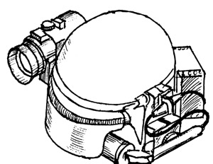
Fig. 13. Head-mounted thermal imaging device
The helmet-mounted combined device is used for the pilot's head-mounted system and for the head-mounted equipment of the «soldier of the 21st century».
Such a device may contain night vision goggles or monocular, a thermal or television device, a display for displaying operational information received from the aircraft's navigation system or from a GPS satellite, a sensor that signals laser irradiation.
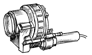
In the simplest case, information from the screen of the cathode-ray tube, which is also mounted on the pilot's helmet (Fig. 14a), is input into the night vision goggles.
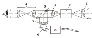
The diagram of the combination of night vision goggles with the TV system is shown in Fig. 14b.
The system in Fig. 14b ensures the input of the image from the EOP screen into the TV system and its subsequent remote transmission via a radio channel. A specific example of such a system is the NW-2000 model from ITT (USA) [37].
In the system, the TV camera is connected to one of the night channels of the night vision goggles for the pilot.
The TV camera is powered by a separate electronic unit with dimensions of 15.24×12.7×5.72 mm, consuming 50 mA from a 12 V or 28 V DC voltage source. The 1/2 inch TV camera has a resolution of 570 (horizontal) x 350 (vertical) TV lines, sensitivity up to 10-3 lux with a signal-to-noise ratio of over 50 dB.
For the NW-2000T and NW-2000W system modifications, the field of view angle is 18×240 and 26×340, respectively, and the weight is 80 g and 105 g.
The TV camera shutter operates with an exposure of up to 1/100,000 s.
The HUD (Head-up Display) model from Elbit (Israel) enters service information into the pilot's night vision goggles according to the diagram in Fig. 13, only the flat mirror 2 is rotated by 900.
The field of view is 32×240, the resolution is 512×512 pixels at an illumination of 10-3 lux, the weight is 110 g, the supply voltage is 28 V DC.
In the so-called “synthetic” night vision goggles according to the diagram in Fig. 15 One of the night channels of the glasses can be combined with a TV camera, the other — with a TV monitor.
This option is also possible in a low-profile design.
Photo 15 shows the appearance of such a system (model ESIG 100) [40].
a)
b)
Fig. 14. External appearance of a head-mounted monocular (a), combined with a TV camera and their optical scheme (b), where 1 is the objective, 2 is the image intensifier, 3, 4 are the eyepiece system, 5, 6 are the conjugating flat mirrors, 7 is the TV camera objective, 8 is the TV camera
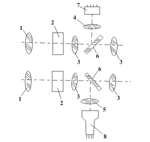
Fig. 15. Scheme of combining binocular night vision goggles with a TV system, where 1 is the objective, 2 is the image intensifier, 3 is the eyepiece system, 4, 5 are the objective of the TV camera or TV monitor, 6 is the conjugating flat mirror, 7 is the TV camera, 8 is the TV monitor
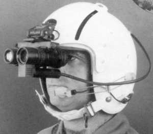
Photo 15. External appearance of aviation night vision goggles combined with a TV system
In a more complex case, night vision goggles are an integral part of the head-mounted (helmet-mounted) display of the integrated observation, piloting and aiming complex.
Such displays embody the technology of “day/night” observation devices, which will be discussed in the next article.
Literature.
1. Volkov V.G. Current state of development of night vision devices. Moscow, Review No. 5576, part 1,2, NTC Informtekhnika, 1994, 202 p.
2. Geykhman I.L., Volkov V.G. Fundamentals of improving visibility in difficult conditions. Moscow, NedraBusinessCenter, 1999, 286 p.
3. Night vision devices. Brochures and price list of GUDP SKB TNV, RF, M., 2000.
4. Salikov V.L. Night vision devices: history of generations.//Special equipment, 2000, No. 2, pp. 40 – 48.
5. Volkov V.G. Night vision devices of new generations.//Special equipment, 2001, No. 5, p. 5 8.
6. Salikov V.L. The era of night war.//Special equipment, 2000, No. 5, pp. 21 – 32.
7. Night vision devices. Prospects of FSUE “Alfa”, RF, M, 2002.
8. Night vision goggles for pilots GEO-ONV1. Prospectus of FPNC NPO “Geophysics NV”, RF, M., May 2002.
9. Cats Eyes. The Unique Aviators night Vision Goggle. Prospectus of GEC Avionics, UK, 1990.
10. Optical arragement. EEC Patent No. 0077193, IPC 3 G02B 27/00, 17/00 with priority from 20.04.83.
11. Night Vision Goggle UK Patent 2100466, IPC 3 G02B 23/12, 23/10 with priority from 29.05.81.
12. Electron-safe aviatorsґ MVGS. Defense Electronics and Computing (Supplement to International Defense Review, 1990, No.2) p. 14.
13. Franck D.L., Geiselman e.e., Craig J.L. Panoramic Night Vision Goggle Flight Test Results. Proceedings of SPIE, 2000, Vol.4021, pp. 146 – 154.
14. Goodman G.W. Future Night Vision. Armed Forces Journal International, 2001, No.1, pp. 22, 24.
15. Hewish M. Image in everthing. JaneТ International Defense News, 2002, Vol.35, No.5, pp. 28 – 25.
16. Mecham M. NASA, USAF Progress On Panoramic Goggles. Aviation Week and Space Technology, 2000, Vol.153, No.7, p. 56.
17. 16mm Image Intensifier. ITT Prospectus, USA, 2000.
18. Night Vision Goggle. US patent No. 5416315 with priority dated May 16, 1995
19. Holographic Night Vision Goggles HNV-3D. Prospectus of OIP, Belgium, 2000.
20. Laser secures troop communication. Laser Focus World, 1996, Vol. 32, No.9, p. 32.
21. Night Vision Goggles GN-1, GN-2. Prospectus of Simrad Optronics, Norway, 1999.
22. Image Intensifier Binocular. EEC Patent No. W087/00639, IPC 4 G02B 23/12 with priority dated 19.07.85.
23. Night Vision Goggles Lucie. Brochure of ANGENIEUX S.A., France, 1999.
24. Jumelle compacte de vision nocturne. French Patent 2721719, IPC 6 G02B 23/12, 23/02 with priority dated 28.06.94.
25. Night Vision Goggle CLARA. Brochure of Sfim, France, 1999.
26. Night vision goggles NV/G-14. Optical devices and instruments. Belomo Catalog. Republic of Belarus, Minsk, 2002.
27. Worldґs First NVG Jumps. Armada International, 1994, Vol.18, No.3, p. 33.
28. Helmet assesed for special forces. Janeґs Defence Weecly, 1994, Vol.21, No.12, p. 22.
29. Holographic Night Vision Goggles HNV-1. Brochure by OIP, Belgium, 2000.
30. Sopelem TN-2 Night Vision Binoculars. Brochure by Sopelem, France, 1998.
31. Low Profile Night Vision Goggle AN/AVS-502. Brochure by Litton, USA, 1999.
32. Volkov V.G. Small-sized television systems. Review No. 5591, M. STC Informtekhnika, 2000, 157 pp.
33. Osterkamp J.B. Enabling technologies in helmet-mounted intensifed cameras. Proceedings of SPIE, 2000, Vol. 4021, pp. 163 – 169.
34. Kamera-Brille Type 88505TV. Prospectus of EMO-Elektronik, Germany, 1999.
35. Volkov V.G., Kovalev A.P., Fedchishin V.G. New generation thermal imaging devices.//Special equipment, 2001, No. 6, pp. 16 – 20, 2002, No. 1, pp. 18 – 26.
36. Miller J.L., Duvoisin H., Wiltsey G. Applications and performance of an uncooled infrared helmetcam. Proceedings of SPIE, Vol. 3436, 1998, pp. 566-571.
37. NW-2000 Night Vision Camera System. ITT Prospectus, USA, 1999.
38. Haixian Z. Synthesized night vision goggle. Proceedings of SPIE, 2000, Vol. 4021, pp. 171-177.
39. ElbitТ's Night Vision Head-Up Display. Prospectus of Elbit Computers Ltd., Israel, 1999.
40. Nur Fliegen ist schoner. Soldat und Technic, 1994, No.7, s. 387.
41. Volkov V.G. “Day-night sight technology”.//Special equipment, 2001, No. 4, pp. 2–7.


Добавить комментарий