Another side of the air show “Maks-2001”..
ZOTOVA Evgeniya Anatolyevna
ANOTHER SIDE OF THE AIR SHOW MAKS-2001”
From August 14 to 19, 2001, the 5th International Aviation and Space Salon MAKS-2001 was held at the airfield of the Gromov Flight Research Institute in Zhukovsky, Moscow Region.
This year, 537 companies from 34 countries took part in MAKS-2001, 30 exhibition pavilions with an area of 11 thousand square meters were open, 4 thousand square meters were allocated for open areas, 52 chalets were reserved.
Russian aircraft technology was presented by 52 companies.
The air show was a record-breaking event in terms of the number of participants and the scale of the display of new technology.
The show also clearly surpassed previous ones in terms of the «influx» of guests and specialists.
According to the organizing committee, the current air show took third place in the ranking of the largest aerospace exhibitions in terms of spectator attendance, behind only Le Bourget (France) and Farnborough (United Kingdom). On the last day alone, the exhibition was visited by about half a million spectators.
It is safe to say that the air show, designed primarily to facilitate the establishment of business and scientific contacts in the aerospace field, turned into a real holiday, which was greatly facilitated this year by the magnificent weather, which gave guests and participants truly summer days.
Bright sun, the smell of shashlik, lots of kids — all this created an indescribable picnic atmosphere.
The show aroused obvious interest not only among specialists, but also among people far removed from aviation. Whole families came. And not only to admire the grandiose air show. General interest was riveted to the latest developments presented at the show.
You can't help but feel a sense of pride when you see unique examples of domestic technology. I won't be wrong if I say that a mixture of fun and pride was the mood that was in the air at the exhibition throughout the week.
The best Russian aerobatic teams took part in the demonstration and show flights: «Rus», «Russian Knights» and «Swifts».
Watching the flights, it was hard to believe that the machines capable of demonstrating light and graceful aerobatics weigh more than one ton. At times, it seemed as if the plane was about to dissolve in the clouds.
But still, I had to tear myself away from this exciting spectacle, no matter how difficult it was to do so. Especially since the main exposition of the exhibition deserved no less attention. Thanks to the thematic diversity of the salon, specialists from a wide variety of fields found a lot of interesting things.
Which is not surprising.
After all, the huge aerospace complex affects not only areas directly related to the development, production and operation of aircraft, but also related areas of activity.
And “MAKS-2001” once again clearly demonstrated this, presenting the entire range of products: from uniforms and equipment for aircraft cabins to the latest developments in the field of aircraft construction.
So technical means of ensuring safety were not forgotten either.
It is these means that will be discussed in the review.
Two large stands were presented by State Research Institute of Instrument-making named after V.V. Tikhomirov” (Zhukovsky), one of them included our magazine.
Among the exhibits, one could see not only weapons control systems for aviation and ground-based systems, but also the OKO series ground penetrating radars already known to our readers (“Special Technology”, No. 2, 2001) and a detector of explosives and other substances based on the NQR method (“Special Technology”, No. 6, 2000).
Interesting developments in the field of remotely piloted aircraft (RPA) were shown by NPKTs Novik-XXI Vek, Moscow and OJSC Kyshtym Radio Plant (Grant complex), as well as State Unitary Enterprise Research Institute KULON, Moscow (RPV Pchela-1).
The Grant complex is designed to monitor terrain and objects on it in real time with digital recording and issuance of the received information to consumers directly or via the Internet.
The GRANT complex implements its purpose by launching up to two UAVs — television observers into the reconnaissance area and transmitting television images from one of them to the mobile control post (MCP) for display and recording.
The range of the command and navigation radio link (CNR) and the television channel for transmitting information of the complex is at least 60 km in conditions of direct radio visibility for the CNR and for the television channel.
Composition of the UAV:
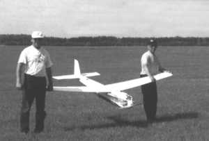
- The glider (photo 1) consists of four modules: a fuselage with an integrated vertical stabilizer, left and right wing consoles and a stabilizer with an elevator.
- The power supply for the UAV onboard equipment is provided by the UAV electric power plant (engine, generator, propeller, resonator-type mufflers) via a secondary power source. The power supply for the UAV equipment during landing with the engine turned off is provided by the battery.
- The central onboard computer is implemented in a single block with the UAV orientation sensor in space and contains a multiprocessor electronic computer, which performs all the main computing functions of UAV control.
- The TRAL module (Television R reconnaissance Apparatur Lgkaya) includes a TRAL computer, which provides control of the electro-optical block, and a television signal transmitter with an antenna.
OAO NOVO (Moscow) took part in the development of the broadband radio link and the electro-optical block.
Photo 1. External appearance of the remotely piloted aerial vehicle
Tactical and technical characteristics of the Grant complex:
|
Composition of the Grant complex (the number of UAVs of the initial delivery is indicated) |
1. PPU on the UAZ-3962 chassis |
| 2. Transport and launch unit (TPU) on the UAZ-3303 chassis. | |
| 3. Two (optional — four) Grant UAVs, stowed in the transport compartments of the TPU | |
|
Target payload (one of the specified) All target payloads for terrain observation contain a broadband transmitter with an antenna |
1. Three TV cameras on a gyroplatform |
|
2. IR scanner of the 8-14 µm range |
|
|
3. IR frame (thermal imager) of 8-14 µm range |
|
|
4. Laser rangefinder-target designator |
|
|
5. Transmitter of special signals |
|
| Order of error in measuring target coordinates (RMS) | Units of meters |
| Optical and acoustic visibility of UAVs | Zero (practically invisible and inaudible) |
| Range (radius), km | 70 |
| Number of simultaneously controlled UAVs | 4 |
| UAV flight duration, h | 3.0…4.0 |
| UAV use altitude range, m | 0…5000 |
| UAV flight speed, km/h | 120 |
| RPV launch weight, kg | 20.0 |
| RPV launch method | Catapult, using the energy of the descending load, without the use of consumables. |
| RPV landing method | Aircraft-based, without the use of any landing devices. |
| RPV use frequency | More than 100 times |
The small-sized complex for reconnaissance and observation of the battlefield in real time with the RPV “Bee-1” is used for aerial reconnaissance, environmental monitoring, as well as for rational use of natural resources, agriculture and forestry, gas and oil industries.
Performs:
- providing consumers with visual information (television or infrared) in real time and at any time of the day;
- operational data exchange with external consumers;
- adjustment of the flight mission in accordance with current consumer requests.
Also on display at the stand of the State Unitary Enterprise Research Institute “KULON” were the KORZ radio search system (a joint development with AOZT “KORZ-CENTER”, Moscow) and a command and information interference-proof radio line for controlling aircraft and transmitting visual information.
Main functions of the KORZ radio search system (operational search and detention of vehicles complex):
- notifying the owner of an attempt to break into the car;
- notifying traffic police posts and patrol car crews of the stolen car data (make, color, state number) indicating the direction of travel and distance;
- stopping the car by radio command from the traffic police post or from the patrol car (ignition lock, hazard warning lights on).
The complex has two radio channels:
- information;
- control.
The information radio channel is designed to notify the owner and police officers about unauthorized entry into the car or an attempted theft.
Through the control radio channel, it sends commands for an emergency stop of a stolen car moving past equipped posts or police cars.
In the event of an emergency stop, the vehicle control channel receiver, having received a coded command from the transmitter of the post or police car, stops the fuel supply or turns off the engine ignition system, and the stolen vehicle stops.
KORZ includes:
- equipment installed in the vehicle;
- equipment located with the vehicle owner;
- equipment installed at posts or police cars.
The vehicle equipment consists of a radio transmitter of the information channel with an antenna, a radio receiver of the control channel with an antenna and an actuator.
The vehicle equipment also includes sensors that respond to unauthorized entry into the vehicle.
The equipment can be powered either from the vehicle battery or from an autonomous source.
The owner's equipment, informing him of a break-in or attempted theft, is a portable radio receiver that operates both from the electrical network and from a built-in autonomous power source.
The equipment of the police post (car) consists of a radio receiver of the information channel with an antenna, a radio transmitter of the control channel with an antenna. The equipment installed at the post is powered from the electrical network through a rectifier built into the equipment. When installed on a police car — from a battery.
The LCD screen displays the state registration number, make, color of the stolen vehicle, as well as the direction and distance to it.
Main tactical and technical characteristics of the KORZ:
| Operating frequency of the information channel, MHz | 163 |
| Operating frequency of the control channel, MHz | 27 |
| Range of the information channel vehicle — police post (car), m | 1000 |
| Operating range of the vehicle – owner receiver information channel, m | 750 |
| Operating range of the control channel, m | 100 |
The command and information interference-proof radio line for controlling aircraft and transmitting visual information ensures the transmission of command, service and visual information and the determination of the navigation parameters of a mobile object.
Main characteristics:
| Digital two-way radio link with noise-like signals | 40 dB base |
| Range | dm |
| Communication range | within radio visibility |
| Information transfer rate: | |
| — command and service, kbit/s | 1,2 |
| — broadband, Mbit/s | 30 |
| Coordinate determination accuracy: | |
| — range, m | ± 15 |
| — azimuth, deg | 0.25 |
| Ground equipment antenna parameters: | |
| — max gain, dB | 12 |
| — field of view, deg | ± 170 |
| — azimuth speed, deg/s | ? 30 |
The onboard and ground equipment modules are structurally identical, their parameters:
| weight, kg | < 6 |
| power consumption in the 27 V circuit, W | < 150 |
The Ryazan State Instrument-making Plant presented the MOST 100/500 atmospheric optical communication line (developed by INTRAST), Ryazan), designed for wireless transmission of digital data between two points with active equipment (photo 2).
It is used as an element of the formation of the information transmission environment when organizing telecommunication networks of integrated services, local area networks, to provide Internet access, connecting automatic telephone exchanges to each other and in other cases when a high-speed and cost-effective solution is needed for transmitting information between spatially separated objects.
Manufacturers note a number of advantages of this communication line:
- does not require frequency range coordination;
- ensures high secrecy and security of transmission;
- absence of mutual interference during simultaneous operation of several systems;
- quick installation (4 – 6 hours) and ease of connection;
- low costs for installation and operation of the system.
Technical specifications:
| Transmitter – laser class 3B according to GOST R 50723-94, radiation power, mW, no more than | 500 |
| Error probability during the channel availability period, BER, no more than | 10-9 |
| Temperature range, ° C: | |
| — PPM (receiving-transmitting module), — KVI (internal interface cable) |
± 40, all-weather |
| — External Interface Device (EID) | +1…35, for indoors |
| Overall dimensions, mm | |
| — PPM | 555х565х240 |
| — EID | 230х45х125 |
| — KVI | length up to 30000 |
| Power supply | 220 V, 50 Hz |
| Power consumption (per post), W, no more than | 15 |
| Warranty period, months, no less than | 12 |
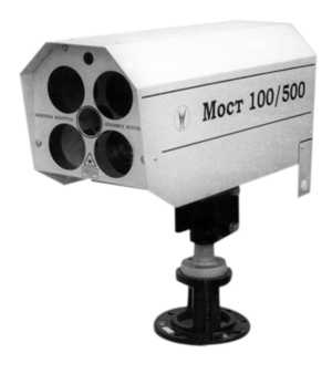
Photo 2. Atmospheric optical communication line MOST 100/500
FSUE Research Institute “STRELA” (Tula) presented radar systems at the exhibition designed for reconnaissance of land and sea targets; border protection, important objects and areas.
“Fara-1” is a small-sized portable radar system (photo 3), designed to detect moving ground targets; automatic weapon guidance in conditions of limited visibility.
| Detection range, km: | |
| — truck | 5 |
| — person | 2 |
| Scanning sector angle, deg | 24, 45, 90, 120 |
| Detection accuracy (target designation): | |
| — by azimuth, mrad | 15 |
| — by range, m | 15 |
| Power consumption, W | 12 |
| Weight, kg | 16 |
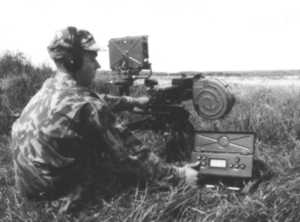
Photo 3. Small-sized portable radar system “Fara-1”
“Monitor-M”, a ground-based radar, is designed for reconnaissance of terrain, border protection, important objects and terrain sections (photo 4).
| Detection range, km: | |
| — truck | 20 |
| — person | 8.5 |
| Scan sector angle, deg: | |
| — in azimuth | 30 – 180 |
| — vertical | ± 18 |
| Detection (target designation) accuracy: | |
| — in azimuth, mrad | 5 |
| — by range, m | 25 |
| Weight, kg | 50 |
| The signal is processed on a computer. |

Photo 4. Ground-based radar “Monitor-M”
“Barrier” is a system for protecting nuclear power plants, weapons depots, oil storage facilities and other important facilities. Includes: a control point, television cameras, air and ground radar sensors.
| Angle of the scanning sector of the protected area, deg | 90 |
| Range of the protected area, m | 320 |
| Probability of intruder detection | 0.95 |
| Continuous operation time | around the clock |
| Maximum distance of system elements from the control point, m | up to 4000 |
Several companies (ZAO NAVIKOM and PRIN-SHOP company, Moscow) presented portable and stationary navigation devices from GARMIN, such as GPS 12, GPS III, and “eTrex” series receivers.
These devices are based on the technology of determining the location using the means of localization of the object based on the global satellite radio navigation positioning system GPS (Global Positioning System).
The presented devices are 12-channel receivers that continuously track and use up to 12 satellites to determine and update coordinates.
The rugged waterproof case of the device GPS 12(photo 5) meets the strict requirements of military standards, a convenient small keyboard allows you to operate the receiver with one hand on the go, regardless of the time of day or weather.
In addition, the receiver provides the ability to record 500 waypoints, memorize up to 1024 points along the route, enter into memory up to 9 “proximity points” that mark dangerous places that it is advisable to bypass when driving, as well as a proprietary innovation — the TracBacka function, which converts the route recording in the opposite direction.
There is a whole range of service navigation functions such as advanced graphics of the moving map, two-speed data output mode, timers of movement along the route.
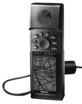
Photo 5. GPS 12 navigation device
GPS III (photo 6) is a global positioning system receiver with an electronic map. It shows not only a map of the area, but also the location.
Contains a built-in international map database containing major cities, roads, lakes and rivers.
The weight of the device is 225 g. GPS III quickly determines the location and displays coordinates, tracks the route and saves the most interesting places with their names, icons and a brief description.
The device screen can display information about the distance traveled and the speed of movement, the time of sunrise and sunset.
A distinctive feature of the receiver is a rotating screen (can be in a vertical or horizontal position).
In addition, aviation GPS navigators (GARMIN) were presented: GPS 92, GPS III PILOT, GPSCOM 190.
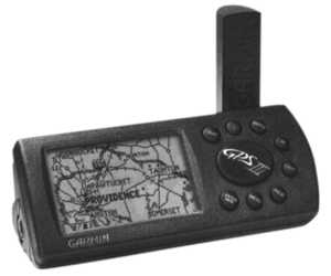
Photo 6. Receiver of the global positioning system GPS III
The problem of preventing terrorist acts, which has become increasingly acute in recent times, makes it especially important to create devices capable of detecting sabotage and terrorist weapons, including in luggage and carry-on luggage.
Such devices are no less important for combating drug smuggling.
Taking this into account, the stand of AOOT “Moscow Radio Engineering Plant”, where one could see the domestic conveyor X-ray system for checking luggage and carry-on luggage “Vizir-1” (photo 7), was of undoubted interest.
Used in “Vizir-1”the algorithm for processing information received from the checked items provides high resolution and a clear image, allowing for easy identification of the checked items, including identifying narcotic and explosive substances, highlighting them in a certain color.
The main advantages of the installation:
- use of an economical and more environmentally friendly pulsed mode of operation of the X-ray generator, allowing two energy levels to be obtained; patent for invention No. 2168229 has been issued for the device for forming a given X-ray spectrum;
- the signal from two energy levels is processed on one line of receivers;
- for a group of organic materials, there is an additional possibility of accurately determining the type of material by its effective atomic number;
- a significant reduction in the dose of X-ray radiation received by items of attachment during baggage inspection.
Standard functions:
- control of objects in the forward and reverse directions of the conveyor belt;
- the ability to obtain negative and positive images;
- the “VZP” function – insertion of prohibited objects to check the professional training of operators;
- electronic marking of baggage;
- the ability to perform gamma correction when the conveyor belt is moving;
- reproduction of only organic objects;
- reproduction of inorganic objects only;
- scaling of any selected zone by 2, 4, 8 times;
- calling up the last two images for repeated study;
- the ability to enter and display on the monitor screen the operator's identification number;
- displaying baggage counter information on the monitor screen.
Photo 7. Conveyor X-ray system for checking baggage and hand luggage «Vizir-1»
On Everest VIT (Germany) demonstrated a portable 6 mm measuring video endoscope VideoProbe XL-PRO a modern portable device for visual and measuring control in industry.
The video endoscope includes:
- CCD color video camera with a resolution of 440,000 dots, 500 HTV lines (HYPER HAD technology);
- Welch Allyn SolarcO 50 W light source with a lamp life of 1,500 hours;
- an ergonomically designed handheld control panel including a high-resolution LCD monitor, a joystick for controlling the probe and a functional video endoscope keyboard.
- combined S-video inputs and outputs for connecting external monitors or recording devices;
- hardware software for image processing and automation of measurement functions.
The device uses the patented ShadoProbe technology of high-precision measurements without loss of resolution, XLPROwareO software for repeated measurements of test objects on a PC.
All this allows the device to:
- Compare the current image with previously archived ones, thanks to the screen splitting system.
- Save images and call them up again on the LCD monitor. The built-in archiving system records up to 48 images on a 3.5″ floppy disk and up to 450 in the internal flash memory simultaneously with recording audio comments via the built-in microphone.
- Enlarge image areas on the screen without replacing the probe lens, using the digital zoom function with a magnification of 1.2; 1.5; 2.0.
And finally, a few words about the measuring instruments presented at the exhibition.
Among the equipment shown by RUDNEV-SHILYAEV CJSC (Moscow), I would like to note the system for directional measurement of acoustic signals and the RF-01 radio spectrum analyzer attachment.
The system of directional measurement of acoustic signals (photo 8) ensures measurement of complex spectra of pressure, velocity, active and reactive components of the intensity of the acoustic field in a given direction.
Application:
1. Measuring the sound insulation of structures.
2. Studying the radiation characteristics of panels.
3. Testing large-sized sound-absorbing samples.
4. Identifying noise transmission paths into the vehicle interior.
5. Localization of noise sources in vehicle interiors and industrial premises.
6. Diagnostics of the technical condition of converters for various purposes using non-contact methods.
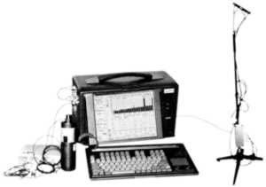
Photo 8. System for directional measurement of acoustic signals
Radio spectrum analyzer attachment RF-01(Photo 9). The spectrum analyzer is designed to monitor radio air traffic, digitally process signals and study the characteristics of radio emissions.
Technical specifications:
| Sensitivity, reduced to the input of the radio receiver (RRU) | not worse than 0.3 μV |
| Dynamic range, reduced to the RRU input | not worse than 100 dB |
| Frequency range | 10 kHz – 2600 MHz |
| Digital filter slope | 72 dB/octave |
| Frequency response flatness in the analysis band | <3 dB |
| Frequency grid resolution | 1 Hz |
| Modulation | AM, FM, USB, LSB&CW |
| Intermediate frequency | 10.7 MHz |
| Analysis bandwidth | 10 MHz |
| Standard filters | 3, 6, 15, 30, 110, 220 kHz |
| Scan rate, MHz/s: | |
| — at 50 kHz resolution | 216 |
| — at a resolution of 6 kHz | 87 |
| — at a resolution of 400 Hz | 5 |
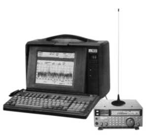
Photo 9. Attachment — radio spectrum analyzer RF-01
Another stand dedicated to measuring equipment belonged to OKTAVA+ company (Moscow).
The large selection of various noise meters, devices for measuring electric and magnetic fields, ionizing radiation, analytical equipment, presented by this company, does not allow us to provide detailed characteristics of all the equipment within the framework of the review.
I will dwell only on some devices.
Thus, for the sanitary and hygienic assessment of noise impact in workplaces, in residential and public buildings, during certification of equipment and vehicles, for measuring room acoustics and conducting scientific research, a portable universal noise meter — spectrum analyzer Larson-Davis 824 (photo 10) is proposed.
Model 824 is designed for the simultaneous measurement of general and corrected sound levels and sound pressure spectra in production, in residential and public buildings.
It can operate in five different modes, allowing you to measure sound pressure levels in all frequency bands simultaneously.
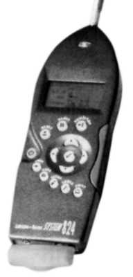
Photo 10. Portable universal noise meter
Larson-Davis 824 spectrum analyzer
Electric and magnetic field meter B&E meter AT-002 (photo 11) is a portable device that allows monitoring the electromagnetic safety standards of video terminals and personal computers.
The amplitude and frequency ranges of the device's measurements comply with SanPiN 2.2.2.542-96.
Registration of electric and magnetic fields is carried out simultaneously in the entire frequency band of measurements.
The device combines in one design two separate meters of electric field intensity and two separate meters of magnetic flux density.
All measured parameters are simultaneously displayed in digital form on a four-line liquid crystal display.
For operation, either the continuous measurement mode of one of the components of the electric field strength and magnetic flux density (search mode) or the absolute value measurement mode of the field vector, including sequential measurement of three components of the electric field strength and three components of the magnetic flux density vector and subsequent calculation of the modulus of these vectors (certification mode) can be selected.
The electric and magnetic field sensors are built into the device body.
The device can be additionally equipped with an external antenna, which makes it possible to certify personal computers in accordance with the international standards MPR II and NCJ 92/25, as well as GOST R 50923-96, GOST R 50949-96.
In conclusion, I would like to note that, in addition to the main topic, the MAKS-2001 air show allowed specialists to get acquainted with a number of interesting developments in various areas of domestic and foreign manufacturers.
The presented exposition, although small, was quite interesting and diverse.

Добавить комментарий