Analysis of the loop parameter of a two-threshold fire alarm control panel. Part 2.
In the first part of the article, in the previous issue of the journal, the characteristics of the loops of the simplest fire alarm control panels (FACP) with high output resistance, about 1 kOhm (Examples 1-3) and with fixed thresholds were analyzed.
The second part of the article presents similar calculations for loops of the fire alarm control panel with current control and a low-resistance output. In addition, more technically complex fire alarm control panels with adaptive thresholds are considered.
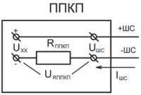
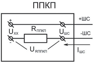
A fire alarm control panel with a loop control by current contains a series-connected current-measuring resistor RППКП of a relatively small value, about 50*250 Ohm.
Unlike the FPCP with loop monitoring by voltage, in which the loop current limitation at a level of about 20 mA is ensured by an output resistance of about 1 kOhm, the FPCP with current monitoring uses an additional circuit for limiting the loop current in short-circuit mode.
Let's continue the analysis of examples of fire loops at different values of voltage UXX, current-measuring resistor RППКП and loop termination resistor RОК.
Let's determine the ranges of loop resistance, currents and voltages for different loop modes at nominal cable resistance RКАБ equal to zero and 220 Ohm, leakage resistance RУТ equal to infinity and 50 kOhm.
We will consider the parameters of the fire alarm control panel itself to be absolutely stable, however, this assumption is obviously not met in practice and, accordingly, it is necessary to have a certain technological reserve to ensure reliable identification of the loop mode, to exclude false alarms and the omission of “Fire” signals.
| Fig. 1. Simplified structure of the current loop output of the fire alarm control panel |
 |
Example No. 4.
Let's consider the parameters of the PPKP loop with a current-measuring resistor RPPKP equal to 100 Ohm, an open loop voltage UXX equal to 15 V, and a loop termination resistor of 3.3 kOhm ± 5%. The nominal current of the loop in standby mode at RОК = 3.3 kOhm, RКАБ = 0 and RУТ = will be IДЕЖ = UХХ/(RPКП + RОК) = 15 V/(0.1 + 3.3) kOhm = 4.41 mA.
Since the current-measuring resistance is insignificant compared to the value of the terminating resistor, the nominal voltage of the loop differs little from the open-circuit voltage and is approximately equal to UШС = 14.56 V. Let us determine the maximum spread of the loop parameters in standby mode.
The maximum value of the standby current is determined with a minimum value of the terminating resistor RОК – 5%, a minimum loop leakage resistance RУТ = 50 kOhm and a cable resistance equal to zero.
In this case, the loop resistance will decrease to 2.95 kOhm, the loop current will increase to 4.92 mA, and the loop voltage will remain virtually unchanged at 14.6 V.
The minimum value of the standby current is determined at the maximum value of the terminating resistor RОК + 5%, at the maximum cable resistance RКАБ = 220 Ohm and the loop leakage resistance equal to infinity.
The loop resistance increases to 3.68 kOhm, and accordingly, the current decreases to 3.68 mA.
Taking these assumptions into account, the loop resistance in standby mode can vary within the range from 2.95 to 3.68 kOhm, the standby current – within the range from 4.92 to 3.96 mA, and the loop voltage remains virtually unchanged, its spread is less than 0.1 V.
| Fig. 2. Loop with normally open detectors |
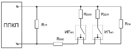 |
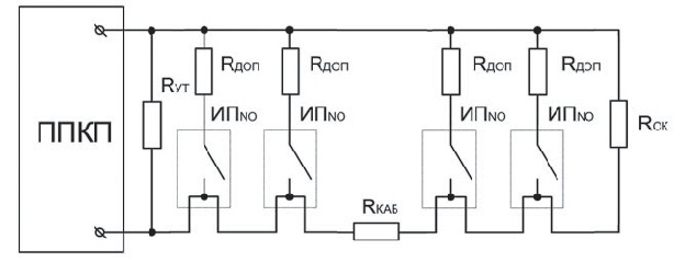
Let's consider a two-threshold loop with detectors with normally open contacts and with additional resistors RДОП = 2 kOhm ± 5% to determine the response of the 1st and 2nd detectors (Fig. 2).
The spread of loop parameters when using 5% resistors is shown in Table 1 and on the graph (Fig. 3).
It can be noted that the nominal currents of the modes are distributed fairly evenly, approximately by 6 mA, a significant standby current implies the possibility of connecting active detectors with a standby current of about 2.5 * 3 mA.
Indeed, since the minimum loop current in standby mode is approximately 4 mA, the loop break mode can be determined at a current of less than 3.5 mA.
The maximum standby current will be equal to 4.92 + 3 = 7.92 mA, i.e. less than the minimum current of the «Fire 1» mode by 9.22 — 7.92 = 1.3 mA, which allows you to set the «Fire 1» threshold at about 8.5 mA.
That is, fairly good loop characteristics are provided, but only in single-threshold mode, without identifying the triggering of the second detector.
In the two-threshold mode, it is necessary to ensure a minimum difference between the current limits of the «Fire 1» and «Fire 2» modes of more than 3 mA. In the example under consideration, according to the calculation results (Table 1), without active detectors, the loop current in the «Fire 1» mode can reach about 12 mA; when adding the standby current of the active detectors of 3 mA, we get a loop current of 15 mA, which confidently falls into the current range of the «Fire 2» mode, the lower limit of which is 13.32 mA.
The current ranges of the «Fire 1» and «Fire 2» modes diverge by only 13.32 — 11.95 = 1.37 mA. Therefore, in the dual-threshold mode with fixed thresholds, the current consumption of the detectors in standby mode must be reduced to approximately 1 mA to ensure identification of the triggering of one and two detectors in the loop.
In Table 1The parameters of the loop for the «Fire 3» mode, which corresponds to the activation of three fire detectors, are also given. The possibility of simultaneous activation of 3 or more detectors in the loop must be taken into account in all fire control panels with a re-query. With a rapid development of the source in a relatively small room and with a significant time delay in checking the loop status after resetting the first triggered detector, it is quite possible that all fire detectors installed in the room will be activated. Naturally, in such a situation, it is unacceptable to generate a «Fault» signal instead of a «Fire 2» signal.
Accordingly, a significant value of the loop short-circuit mode threshold must be set in the fire control panel, for example, about 30 mA (Table 1).
If we assume that the probability of a short circuit in the loop several tens of seconds after the activation of the first fire detector is zero, then we can set the logic of the device operation in such a way that after a re-query of the loop status, even at currents corresponding to a short circuit, the “Fire 2” signal is generated.
| Fig. 3. Dispersion of loop parameters with normally open NO detectors |
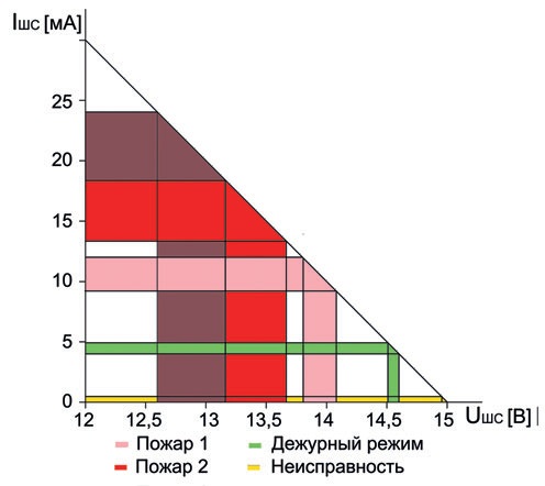 |
Table 1
|
|
Loop break |
Standby |
Fire 1 mode |
Fire 2 mode |
Fire 3 mode |
Short circuit |
|
|
Resistance |
min. nom. max. |
50 infinity infinity |
2.95 |
1.16 |
0.72 |
0.52 |
0 0 |
|
Loop current, mA |
min. nominal . max. |
0.3 0 |
4.92 |
11.95 |
18.32 |
24.14 |
150* |
|
Voltage |
min. nominal. max. |
14.97 |
14.51 |
13.81 |
13.17 |
12.59 |
0 0 |
*) Without taking into account the additional loop current limiting circuit
Table 2
|
|
Loop break |
Standby |
Fire 1 mode |
Fire 2 mode |
|
|
Cable resistance |
min. nominal. max. |
50 infinity infinity |
2.95 |
1.16 |
0.72 |
|
Current loop, mA |
min. nominal. max. |
0.3 0 |
4.92 |
11.95 |
18.32 |
|
Voltage |
min. nominal. max. |
14.97 |
14.51 |
13.81 |
13.16 |
Table. 3
|
|
Break |
Standby |
«Fire 1» mode |
«Fire 2» mode |
|
|
Resistance |
min. nominal. max. |
50 infinity infinity |
3.07 |
1.20 |
0.75 |
|
Loop current, mA |
min. nominal. max. |
0.3 0 |
4.74 |
11.51 |
17.68 |
|
Voltage |
min. nominal. max . |
14.97 |
14.53 |
13.88 |
13.23 |
Example No. 5
Analyzing the data given in Table 1, it can be noted that in standby mode, the leakage resistance and cable resistance have approximately the same effect on the loop parameters: the loop current increases or decreases by approximately 0.5 mA.
But in the «Fire 1» mode, and especially in the «Fire 2» mode, with a decrease in the loop resistance, the leakage resistance of 50 kOhm connected in parallel has an ever-lessening effect, and the series-connected cable resistance of 220 Ohm increasingly reduces the loop current compared to the nominal values.
For example, in the «Fire 1» mode, the loop current can increase by 0.8 mA due to leakage and decrease by 1.93 mA due to cable resistance and the spread of resistor ratings.
In the «Fire 2» mode, the current can increase by 1.03 mA, and decrease by almost 4 mA! By GOST R 53325-2009 «Fire-fighting equipment. Technical means of fire-fighting automation. General technical requirements. Test methods» Item 7.2.1.4 «The maximum resistance of the wired communication line (alarm loop) without taking into account the resistance of the remote element, at which the fire alarm control panel must remain operational, is selected from the following range: 0.10; 0.15; 0.22; 0.33; 0.47; 1.00 kOhm.
For addressable fire alarm control panels — 50 Ohm. The minimum leakage resistance between the loop wires and between each wire and the «Ground», at which the fire alarm control panel must remain operational, must be no more than 50 kOhm.»
Without significantly limiting the practical application of non-addressable fire alarm control panels, the maximum loop resistance can be reduced to 100 Ohm.
Even when using a cable with a minimum permissible core diameter of 0.5 mm, the loop length can reach about 500 m. By reducing the permissible cable resistance, the spread of loop parameters is significantly reduced (Table 2).
In this case, the spread of currents in the «Fire 1» and «Fire 2» modes decreases by approximately 2 times, and the difference between the maximum loop current in the «Fire 1» mode and the minimum current in the «Fire 2» mode increases to approximately 3 mA.
Accordingly, if we determine the standby current of active detectors to be 2 mA, then there remains a technological reserve of approximately 1 mA for reliable identification of the triggering of one or two detectors in the loop.
The minimum standby current due to the loop end resistor remains significant, more than 4 mA.
This allows you to set the loop fault threshold for open circuit at 3 mA.
Accordingly, with a detector current of 2 mA and a loop leakage current of 0.3 mA, the total loop current in the «open circuit» mode is 2.3 mA, and the loop fault will be unambiguously determined.
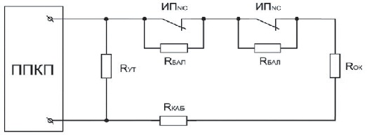
| Fig. 4. A loop with double triggering with normally closed detectors for opening RБАЛЬ = 1.2 kOhm, RОК = 2.4 kOhm |
 |
| Fig. 5. Spread of parameters of a loop with normally closed NC detectors |
 |
Further reduction of the loop parameter spread can be achieved by using precision 1% resistors. In this case, the difference between the maximum loop current in the «Fire 1» mode and the minimum current in the «Fire 2» mode increases to 3.87 mA, and the loop currents of the standby mode and the «Fire 1» mode diverge by 5.55 mA (Table 3).
If a precision 1% resistor is used only as the end element of the loop, and the remaining resistors are taken, as usual, with 5% accuracy, then we will also get a gain, but not as significant. The difference between the maximum loop current in the «Fire 1» mode and the minimum current in the «Fire 2» mode in this case will be 3.24 mA, and the loop currents of the standby mode and the «Fire 1» mode diverge by 5.34 mA.
Example No. 6.
The first part of the article showed that including detectors for closing and opening in one loop leads to a significant deterioration in the loop parameters.
In addition, it is always assumed that in a combined loop, either smoke detectors are triggered, and the loop resistance decreases, or heat detectors, and the loop resistance increases, i.e. the fire alarm control panel is not designed in principle to identify simultaneously triggered different types of detectors.
And the occurrence of such an event becomes quite real after a re-query of the loop status, after the activation of the first detector.
From the point of view of increasing fire safety, it is advisable to allocate a room protected by heat detectors with normally closed contacts into a separate zone and protect it with a separate loop excluding the request-override function to ensure the fastest possible detection of the source.
Figure 4 shows the structure of a loop with fire detectors for opening.
We will accept the initial characteristics, as before: UXX = 15 V, RППКП = 100 Ohm, and we will reduce the nominal value of the end-of-line resistor RОК to 2.4 kOhm ± 5% to increase the loop current in standby mode.
The maximum loop cable resistance and the minimum leakage resistance are taken to be 220 Ohm and 50 kOhm, respectively. The loop parameters for the minimum, nominal, and maximum loop resistance for different modes are given in Table 4.
The loop current ranges corresponding to different modes do not intersect, but it can be noted that the boundaries of the «Fire 1» and «Fire 2» modes are almost the same (Fig. 5).
The minimum loop current in the «Fire 1» mode is 3.66 mA, and the maximum loop current in the «Fire 2» mode can reach 3.51 mA, i.e. these modes differ by only 0.15 mA and with minor threshold deviations, an identification error of the triggering of one or two detectors is possible.
To ensure a technological reserve, we use a precision 1% resistor with the same nominal value of 2.4 kOhm as the end element of the loop. The calculation results for this case are given in Table 5.
Table 4
|
|
Breakage |
Fire 2 mode |
Fire 1 mode |
Standby |
Short circuit | |
|
Resistance |
min. nominal. max. |
50 infinity infinity |
4.18 |
3.20 |
2.18 |
0 0 |
|
Loop current, mA |
min. nominal. max. |
0.3 0 |
3.51 |
4.54 |
6 .58 |
150* |
|
Voltage |
min. nominal. max. |
14.97 |
14.65 |
14, 55 |
14.34 |
0 0 |
Table 5
|
|
Breakage |
Fire 2 mode |
Fire 1 mode |
Standby |
Short circuit |
|
|
Resistance |
min. nominal. max. |
50 infinity infinity |
4.26 |
3.28 |
2.27 |
0 0 |
|
Loop current, mA |
min. nominal . max. |
0.3 0 |
3.44 |
4.43 |
6.58 |
150* |
|
Voltage |
min. nominal. max. |
14.97 |
14.66 |
14.56 14.59 |
14.37 |
0 0 |
*) Without taking into account the additional loop current limiting circuit
Table 6
0.75
–
1.02
13.83
–
14.03
0
0
10.31
|
|
Standby |
|
Fire 1 mode |
 |
Fire 1 mode |
|
|
Cable resistance |
min. nominal. max. |
3.52 |
|
1.23 |
||
|
Loop current, mA |
min. nominal. max. |
4.14 |
7.10 |
11.24 |
6.45 |
17.69 |
|
Voltage |
min . nominal value. max. |
14.57 |
||||
The minimum current of the «Fire 1» mode loop increased to 3.75 mA, and the maximum current of the «Fire 2» mode decreased to 3.44 mA, thus their difference increased to 0.31 mA. At the same time, the current areas of the standby mode and the «Fire 1» mode diverge by approximately 1 mA.
Example No. 7.
Let's consider a loop with adaptive thresholds. When the system is started, the fire alarm control panel remembers the standby mode currents of each loop and adjusts the mode thresholds accordingly.
The most advanced fire alarm control panels additionally have a function for programming thresholds taking into account the detector currents in fire mode.
However, the adaptation capabilities have their limits, i.e. not all variations in loop parameters can be compensated, in addition, the compensation range also has its limits, which are determined by technical solutions.
Obviously, as “non-compensable” parameters, it is necessary to take into account the random spread of additional resistors of fire detectors in total with the resistance of the cable, which varies within the length of the loop.
Let's consider a loop with normally open detectors.
We will take the main parameters from Example No. 4, but we will consider detectors connected at the beginning of the loop with additional resistors of the minimum value RДОП = 2 kOhm – 5% = 1.9 kOhm, and at the end of the loop with resistors of the maximum value RДОП = 2 kOhm + 5% = 2.1 kOhm, within the spread of ±5% (Fig. 6).
With the output resistance of the device RППКП = 100 Ohm, open loop voltage UХХ = 15 V, cable resistance RКАБ = 220 Ohm and loop terminating resistor RОК = 3.3 kOhm, the nominal current of the standby mode will be 4.14 mA.
The spread in the resistance of the terminating resistor is compensated for during the adaptation process.
In the «Fire 1» mode, when one detector at the end of the loop is activated, the current increases to 9.36 mA, when the detector at the beginning of the loop is activated, it increases to 11.24 mA (Table 6).
In the «Fire 2» mode, when two detectors are activated at the end of the loop, the current is 13.43 mA, when two detectors are activated at the beginning of the loop, it increases to 17.69 mA.
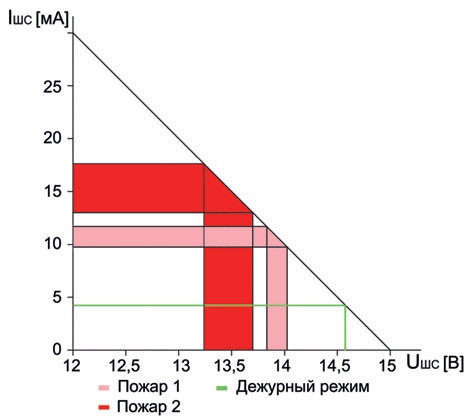
Thus, in the worst case, in the area of currents of the «Fire 1» and «Fire 2» modes, they are spaced by more than 2 mA, regardless of the value of the standby current of the detectors 0*3 mA (Fig. 7).
In the fire alarm control panel with adaptive thresholds, changes in the loop current are essentially analyzed, and the nominal value of the terminating resistor can be selected based on the required value of the standby current reduction when the loop is broken.
For example, increasing the terminating resistor to 7.5*10 kOhm provides a significant reduction in the standby current. A break in the loop is identified by the control panel when the loop current decreases by 1.5*2 mA due to the disconnection of the terminating resistor.
Moreover, devices with adaptive thresholds can implement a function for compensating for the standby current drift with the formation of fault signals when the limits of the auto-compensation range are reached.
Which allows automatic detection of increased loop resistance during operation, for example, caused by corrosion, deformation of contacts or poor installation.
| Fig. 6. Loop with normally open detectors |
 |
| Fig. 7. Variation of loop parameters with adaptive thresholds |
 |
In conclusion, it should be noted once again that clause 7.2.1.5 of GOST R 53325_2009 states that “the fire alarm control panel must have the following designation indicators, the numerical values of which are provided in the technical documentation (TD) for the fire alarm control panel:
- maximum resistance of the alarm loop excluding the resistance of the remote element, at which the fire alarm control panel remains operational (for fire alarm control panels with wired communication lines);
- minimum leakage resistance between the wires of the alarm loop and between each wire and the “Ground”, at which the fire alarm control panel remains operational (for fire alarm control panels with wired communication lines);
- current ranges in a non-addressable alarm loop, including the maximum current supplying the detectors at which the fire alarm control panel registers all the provided types of notifications.»
Currently, in violation of the requirements of GOST R 53325_2009, the documentation for the fire alarm control panel, as a rule, only provides the loop resistance limits corresponding to various modes, without specifying the corresponding loop currents.
The maximum current consumption of fire detectors in standby mode is separately indicated, which often exceeds the current of the «loop break», which does not ensure the registration of all the provided types of notifications.
In addition, the lack of information in the documentation on the modes of the fire alarm control panel depending on the loop current does not allow for the correct determination of the permissible current of the detectors in standby mode and the assessment of the compatibility of the device with fire detectors of various types, especially with smoke fire detectors with a non-linear volt-ampere characteristic, but this is the topic of the next article.
Here it would be a good idea to have in the documentation for the fire alarm control panel the values of the current thresholds for the maximum number of any specific fire smoke detectors with the maximum cable resistance, indicating the corresponding values of the loop voltage, which will allow users to predict the behavior of the loops for other types of fire detectors.
In practice, to check the registration of all the envisaged types of notifications, it is recommended, in addition to disabling the last fire alarm in the loop, to activate the first and second alarms at the beginning of the loop and the first and second alarms at the end of the loop.
Using this technique will to some extent allow checking the formation of the «Fire 1» and «Fire 2» signals taking into account the cable resistance even in adaptive fire alarm control panels.
_____________________________________________
I. Neplokhov
Ph.D., Technical Director of the Business Group «Center’SB»
LITERATURE
1. Neplokhov I. Analysis of the parameters of the loop of a two-threshold fire alarm control panel //»Algorithm of Security», No. 5, 2010.
2. Bakanov V. The key to high-reliability fire alarm systems //»Security Algorithm», No. 6, 2010.
3. Neplokhov I. Classification of non-addressable loops, or Why there are no two-threshold devices abroad //»Security Algorithm», No. 3, 2008.
4. Pinaev A., Nikolsky M. Assessment of the quality and reliability of non-addressable fire alarm devices //»Security Algorithm», No. 6, 2007.
magazine «Security Algorithm» No. 6, 2010
