Active-pulse night vision devices.
VOLKOV Viktor Genrikhovich,
Candidate of Technical Sciences, Associate Professor
ACTIVE-PULSE NIGHT VISION DEVICES
The operation of active-pulse (AP) NVDs is based on the pulse observation method proposed by Academician A.A. Lebedev in 1936 [1].
The essence of the method is as follows.
The object of observation is illuminated by short light pulses, the duration of which is significantly less than the time it takes for light to travel to the object and back.
In this case, the object is observed in an optical device equipped with a fast-acting shutter that opens in time with the sending of light pulses for a certain time.
In the case where the time delay between the moment of emission of the pulse and the moment of opening of the shutter is equal to twice the time required for the light to travel the distance to the object and back, the observer will see only the object itself and the area of space immediately surrounding it.
The depth of this space is determined by both the open time of the shutter and the duration of the light pulse.
This method was later described in foreign literature, where it is usually called the Gated Viewing method.
To implement this method, a pulse illuminator generating sufficiently short light pulses is required, as well as an image converter equipped with a fast shutter.
Initially, a lamp spotlight was used as such an illuminator, and a conventional image intensifier tube was installed in the receiving part of the equipment.
The pulse mode of operation of the receiving part was ensured either by installing a fast-acting Kerr or Pockels shutter in front of the photocathode of the image intensifier tube, or by pulse control (strobing) of the image intensifier tube directly by the high-voltage supply voltage.
The use of the specified gates resulted in unjustified energy losses, and strobing by supply voltage required vacuum tube electronic units with significant weight, dimensions and energy consumption.
At the end of the 40s, M.M. Butslov and his team managed to develop pulsed image intensifier tubes with a compensated gate [1].
The use of these image intensifier tubes made it possible to significantly simplify the strobing unit and reduce its weight, dimensions and energy consumption.
In 1950, on the initiative of A.A. Lebedev, work began at the State Optical Institute (GOI) of the USSR to create the first samples of AI observation devices.
A searchlight made on the basis of a reflector with a diameter of 1500 mm and a detachable argon flash lamp GOI with a pressure of 4-6 atm, a frequency of 500-800 Hz and an average radiation power of 2-3 kW [1] was used as a pulse illuminator.
The receiving part of the equipment used a lens with a focal length of 600 mm and a relative aperture of 1:1.6, a pulsed image intensifier UZ-42 and an eyepiece with a magnification of 4x. The range of recognition of objects on the sea surface was over 15 km.
At the same time, the weight, dimensions and power consumption of the equipment remained significant due to the lamp spotlight. The divergence angle of its radiation was also large, which reduced the light intensity and limited the range of the device.
Since it was not possible to increase the brightness of pulsed plasma light sources above certain limits, it was also unrealistic to improve the parameters of the device.
Significant progress in the development of AI NVD was achieved only in the early 1960s in connection with the creation of lasers.
Compared to spark lamp sources, lasers have significant advantages:
- high brightness and directivity of radiation;
- monochromaticity of radiation, allowing the use of narrow-band filters in the receiving part of the device, cutting off the radiation of light interference;
- short duration of radiation pulses (units and tens of hertz), allowing to obtain comparatively small depths of the viewed space, measured in fractions and units of meters. This allowed to sharply increase the image contrast in strongly scattering media (haze, fog, rain, snowfall, water, etc.). In this regard, the most favorable results were obtained using solid-state lasers operating in the modulated Q mode and generating the shortest powerful radiation pulses with a duration of 20 — 50 ns.
The first work with AI devices using lasers was carried out at GOI in 1963. A ruby laser operating in Q-modulated mode provided pulse energy of 0.5 J with a radiation pulse duration of 30 ns.
The receiving part of the equipment used a pulse image intensifier with a compensated shutter and a lens with a focal length of 1000 mm and a relative aperture of 1:7. The equipment allowed observing a truck at night at a distance of up to 1 km.
The error in measuring the distance did not exceed 5 m. A shield with a star cut out on it was installed at a distance of approximately 800 m from the device. A curtain made of multilayer gauze was hung in front of the shield to imitate air haze.
When observing at night with a regular passive device, and during the day with an optical device (binoculars), the image of the star is not visible.
But the use of the AI mode allowed us to «cut off» the gauze, and a clear image of the star appeared. During the tests on a clear sunny day with a natural illumination level of 5×10⁴ lux, the observation object was recognized at a distance of 1.2 km.
Successful observation tests were also conducted in heavy rain, fog, and in the presence of a cloud between the device and the observation object. An interference filter with a passband of 3 nm was installed in the receiving part of the equipment.
Later, GOI used neodymium glass lasers with doubled and non-doubled frequency, operating in frequency or monopulse Q-modulated mode, as well as in a more favorable spike generation mode with a spike pulse duration of 200 ns.
The strobe duration was about 1 μs. The work [2] presents the results of both domestic and foreign work on the creation of AI equipment.
It was used for high-speed photography, aerial photography, underwater vision. In the latter case, the viewing ranges ranged from several dozen to 300 m.
The description of underwater vision systems based on AI NVG can serve as the topic of a separate article.
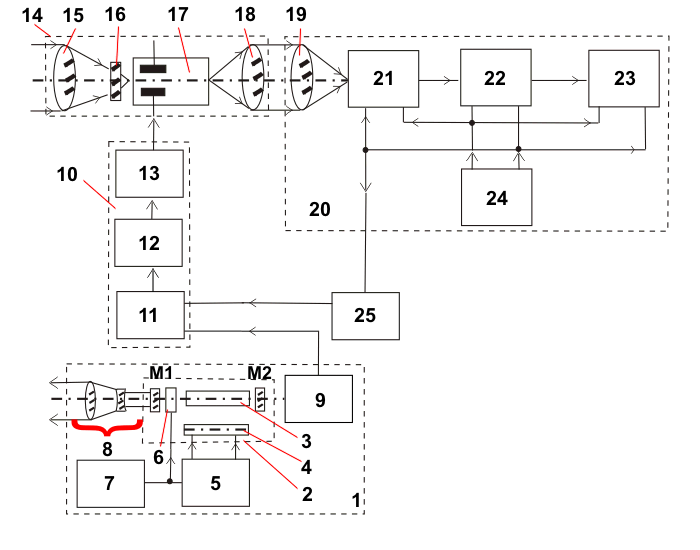
The block diagram of the AI NVG using solid-state lasers is shown in Fig. 1.
The device operates as follows.
The active medium 3 of the emitter 2 functions in the pulse laser illuminator 1.
The active medium 3 is excited by the radiation of the pump lamp 4, driven by its power supply unit 5.
The generation of laser radiation is maintained by mirrors M1 and M2 of the resonator.
The Q-modulator 6, driven by its power supply unit 7, creates the Q-modulation mode.
The optics 8 form the required illumination angle and direct the radiation of the illuminator 1 to the observation object. The radiation pulses, reflected from the object, enter the observation unit 14.
The lens 15 forms an image of the object on the photocathode of the pulsed image intensifier tube 17. The filter 16 serves to cut off the measurement of light interference acting in a wide range of the spectrum.
Before the radiation pulse arrives at the photocathode of the image intensifier tube 17, the latter's shutter is locked. At the moment of arrival of the radiation pulse reflected from the object of observation, the image intensifier tube shutter is unlocked for a time equal to or slightly exceeding the duration of this pulse.
To ensure the specified synchronous operation of the illuminator 1 and the observation unit 14, a photodetector 9 is used, converting part of the energy of the laser radiation pulse into a pulsed electrical signal, which starts the master pulse generator (MPG) 11, operating in the standby mode.
The MPG 11 generates synchronizing pulses, which are delayed in the adjustable delay unit (ADU) 12 for a time equal to the passage of the radiation pulse distance from the device to the observation object and back.
From the output of BRZ 12, the sync pulse excites the strobe pulse generator (SPG) 13, which creates strobe pulses that unlock the shutter of the image intensifier tube 17.
The latter enhances the image in brightness, converting it into a visible one.
The operator observes the image through the eyepiece 18.
The operator, smoothly adjusting the delay, can move the narrow zone of the viewed space in depth until the observed object falls within its limits.
1 – pulsed laser illuminator, 2 – pulsed laser emitter, 3 – active medium; M1, M2 – resonator mirrors, 4 – pump lamp, 5 – its power supply unit, 6 – Q-modulator, 7 – its power supply unit, 8 – radiation shaping optics (Galileo telescopic system), 9 – photodetector, 10 – control and synchronization unit, 11 – ZGI, 12 – BRZ, 13 –FSI, 14 – observation unit, 15 – objective, 16 – filter, 17 pulse image intensifier tube, 18 – eyepiece (or first component of transfer optics), 19 – second component of transfer optics, 20 – TV channel, 21 – transmitting TV camera, 22 – video amplifier, 23 – TV monitor, 24 sync generator, 25 – line frequency division unit (elements 19–25 are missing for eyepiece image output).
Fig. 1. Block diagram of the AI NVD using a pulse illuminator based on a solid-state laser.
If TV channel 20 is installed at the output of observation unit 14, the image from the image intensifier tube screen is transferred to the light-sensitive element of transmitting TV camera 21 using the first 18 and second 19 components of transfer optics.
TV camera 21 converts the image into an electrical signal, which is amplified in video amplifier 22 and transmitted to TV monitor 23, where the video signal is converted into an optical image.
Sync generator 24 serves for frame and line synchronization of operation of units 21 – 23, as well as for synchronization of ZGI 11.
To perform the latter function, the line frequency signal from the synchronization generator 24 is fed to the frequency division unit 25, which divides the line frequency to a level close to the operating frequency of the illuminator 1 and a multiple of it [1].
However, the minimum dimensions, weight, power consumption, as well as the highest performance indicators were achieved by using illuminators based on pulsed laser semiconductor emitters (PLSE) in the AI NVG.
In Russia, in 1962-1964, experimental AI equipment using ILPI was first developed at the Research Institute of Applied Physics on the initiative of Corresponding Member of the USSR Academy of Sciences L.N. Kurbatov.
The first ILPI samples required cooling with liquid nitrogen, which forced the use of either a gas Stirling refrigeration machine or an open cooling system. This was unacceptable for the practical use of the devices.
In the late 1960s – early 1970s, ILPI models appeared that did not require cooling, and combining individual emitters into multi-element arrays made it possible to achieve average radiation powers sufficient to achieve the required ranges.
In connection with this, not only mock-up models, but actually used AI devices appeared in Russia and abroad [1].
It was reported [1] that the company Laser Diode Laboratories (LDL), USA, developed an AI NVD with a range of up to 100 m.
The weight of the device held in the hands was 6.8 kg.
The device allowed to see objects and measure the distance to them both in normal atmospheric transparency and during rain, fog and snowfall. A similar device, but with a range of 300 m, was developed at the State Unitary Enterprise NPO Orion in 1972.
The block diagram of the AI NVD with an illuminator based on the ILPI is shown in Fig. 2.
It works in the same way as the NVD shown in Fig. 1, only the ZGI 6 is triggered by sync pulses from the pumping unit 4, from the other output of which the ILPI 3 is excited by current pulses, generating radiation pulses of equal duration.
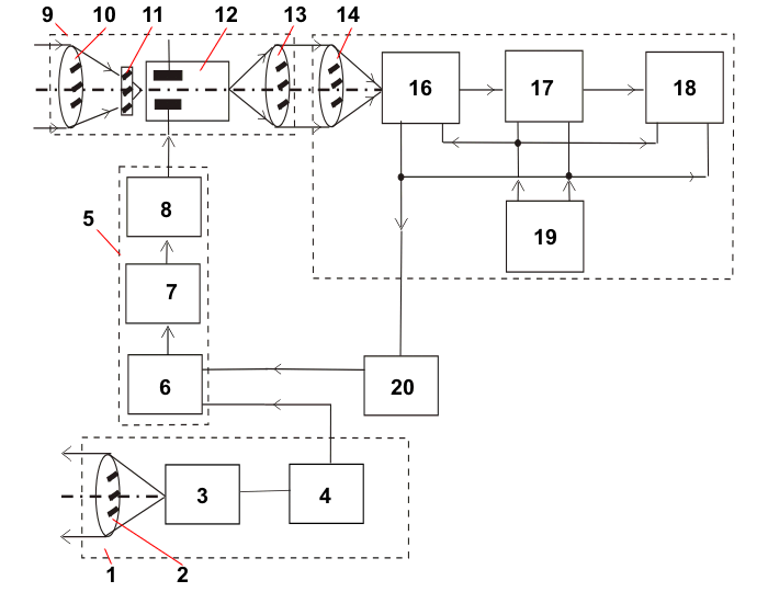
1 – pulsed laser illuminator, 2 – beam forming objective, 3 – ILPI, 4 – its pumping unit (current amplifier on semiconductor elements), 5 – control and synchronization unit, 6 – ZGI, 7 – BRZ, 8 FSI, 9 – observation unit, 10 – objective, 11 – band-pass (or cut-off) filter, 12 – pulsed image intensifier, 13 – eyepiece (or first component of transfer optics, if the image is input into the TV channel), 14 – second component of transfer optics, 15 – TV channel, 16 – transmitting TV camera, 17 – video amplifier, 18 TV monitor, 19 – sync generator, 20 – line frequency division unit.
Fig. 2. Block diagram of the AI NVD using an illuminator based on a pulsed laser semiconductor emitter (PLSE):
AI NVDs, regardless of the block diagram, allow increasing the contrast in the image of the observed object, and therefore the range of the device due to:
- cutting off the backscatter radiation by delay, which in conventional active NVDs is superimposed on the image of the observed object and reduces the contrast in its image even with normal or slightly degraded atmospheric transparency;
- attenuation, equal to the duty cycle of the device, of radiation scattered in the atmosphere, determined by the level of natural illumination.
This radiation in conventional passive NVDs with reduced atmospheric transparency also sharply reduced the contrast in the image of the observed object.
Photo 1 shows the nature of observation in an AI NVD at night in fog of a full-length model of a human figure when the device is operating in passive (a), active-continuous (b) — the illuminator is working, the shutter of the image intensifier is open — and AI modes (c). The advantage of the AI mode is obvious here. Photo 2 shows an image of a tank (a), an inflatable boat (b) and a human figure next to its model (c) when the device is operating in AI mode.
Photo 1. The nature of observation in the AI NVG at night in fog of a full-length model of a human figure when the AI NVG is operating in:
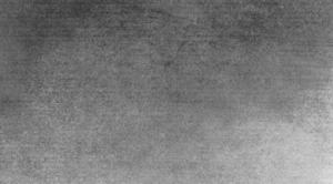
a) passive;
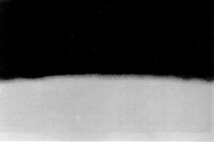
b) active-continuous – the illuminator is working, the shutter of the image intensifier is open;
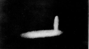
c) active-pulse modes.
Photo 2. The nature of observation in the AI NVD when it is operating in the AI mode:
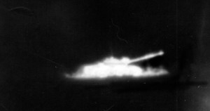
a) a tank (side);
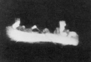
b) an inflatable boat with two rowers (side);
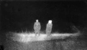
c) a full-length figure of a person next to its target.
Since the object of observation is perceived within a very narrow depth of the viewed space, the background behind the object is cut off.
This allows observing low-contrast objects that are not visible either at night in passive or active optical-electronic devices, or even during the day in conventional optical observation devices.
For example, in the AI NVG, snow structures (ramparts) or figures of people in white coats against the background of virgin snow were clearly visible. This opens up great opportunities for using the AI NVG for rescuers or for exploration of natural resources, for example, to distinguish coal against the background of rock.
Since the image of the object of observation appears only with a certain delay value, directly proportional to the distance to the object, then the distance to the object can be measured by the delay value.
The accuracy of range measurement usually reaches ±10 or ±5 m, but if necessary it can be at least an order of magnitude higher.
This accuracy does not depend on the distance to the object, but is determined only by the duration of the strobe pulse and the illumination pulse.
Unlike conventional laser rangefinders, the AI NVG eliminates the possibility of issuing a false range value due to the rangefinder's reaction to random objects located between the useful object and the device (for example, tree branches, wires, etc.), the signal from which can significantly exceed the signal from the useful object.
In the AI NVG, all these false signals are cut off by a delay.
Due to operation in pulse mode, any long-term light interference (radiation from spotlights, headlights, fire flames, etc.) is weakened by a number of times equal to the duty cycle of the device (provided that the shutter of the image intensifier is locked reliably enough). This is how the observed object is time-selected against the background of interference.
Additional noise immunity is achieved by using a bandpass (or cutoff) filter in the observation unit with a passband corresponding to the working range of the laser illuminator spectrum.
The actual values of the degree of protection against interference due to the specified spectral-temporal selection can reach 105 — 107.
This is sufficient to ensure that observation is not disrupted when the device is exposed to a floodlight with a luminous intensity of up to 4×10⁶ cd, as well as for observation in daytime conditions with a natural illumination level of 5×10⁴ — 105 lux — a clear sunny day.
Thus, the AI mode allows for round-the-clock observation.
Changing the delay value allows you to select either the illuminated observation object or the illuminated near background behind it.
In the first case, the operator sees a light object on a dark background — an image of the object in «positive» contrast. In the second case, a dark silhouette of the observed object on a light background — an image of the object in «negative» contrast.
From an energy point of view, it is more advantageous to observe in «negative» contrast, since natural backgrounds usually have a higher luminance coefficient than the observed object, and, therefore, to achieve the required range of action, a lower illuminant power is required.
However, many informative features of the object are lost, since only its silhouette (outer contour) is visible, and the lower part merges with the background.
In addition, there may be no near background (if the object is projected against the sky, for example), so the most universal observation is in «positive» contrast, for which all data on the range are usually provided.
The NVD can operate in passive, active-continuous and active-pulse modes (depending on external conditions).
The disadvantage of the AI mode is the limited depth of the viewed space, determined by the strobe duration, and also the fact that the field of view in the AI mode is equal only to the illumination angle of the laser illuminator.
For energy reasons, this angle cannot be large and usually does not exceed 1 – 3°.
Thus, to detect the observed object, it is necessary to search both by field and by depth, which leads to completely unacceptable time costs. Therefore, the search is usually carried out in a wider-field passive mode.
The detection range of an object is usually 1.3 — 1.5 times greater than its recognition range. Therefore, in passive mode, the object is only detected, and its recognition and range are measured in the AI mode, which has an advantage over the passive mode in terms of range.
If this is impossible due to low illumination, then the search is conducted in an active-continuous mode, and in case of low transparency, an additional search channel is used.
24-hour search for objects can be conducted by glare of laser radiation reflected from optical or optoelectronic means of these objects.
The range of detection of objects by glare can reach several kilometers [2].
The Transcript company (RF) has developed such an AI NVG Mirage-1200” with a glare detection range of 1200 m, with a field of view angle of 4.5?, a weight of 2.1 kg, and a power consumption of 13 W [3].
It is also possible to use the so-called «hybrid» mode, which combines passive, active-continuous and AI modes. The hybrid mode is optimal when using AI NVDs for driving a vehicle.
In recent years, AI NVDs have received image output to a TV channel, most often based on a CCD matrix.
At the same time, the TV AI NVD of the Platan Research Institute [4], based on a pulsed semiconductor laser with electron beam pumping, deserves attention.
The visibility range in TV AI NVG is 5–1000 m, the depth of the viewing space is 3–30 m, the field of view angle is 1.5–15?, the radiation power in the pulse is 10–15 MW, the duration of the illumination pulse is 5 ns, the resolution is 350 TV lines [4].
In photos 3–7 and Fig. 3, 4 show the appearance of typical AI NVGs.
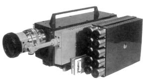
Photo 3. Appearance of the portable AI NVG of the GUDP SKB TNV:
on the right – a ten-module illuminator based on the ILPI,
on the left – an observation device.
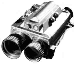
Photo 4a. Appearance of the portable
AI NVD “Filin-130” (NVD-130);

Photo 4b. Appearance of the portable AI NVD DM-740.
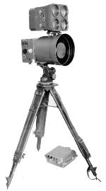
Photo 5. Appearance of the portable AI NVG of the Central Design Bureau Tochpribor.”
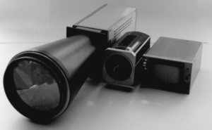
Photo 6a.. Appearance of TV AI NVG GUDP SKB TNV;
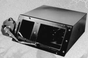
Photo 6a.. External appearance of the NORD Lynx TV AI NVG
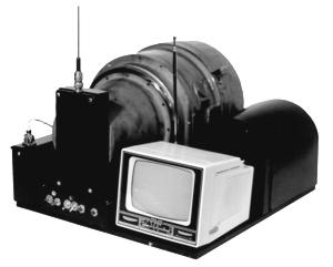
Photo 7. External appearance of the Berkut TV AI NVG
with remote image transmission.
Video and Optical Systems Ltd. (Great Britain) has developed a sample of such a TV AI NVG based on a CCD matrix with 610×575 elements [1] (Fig. 3).
Camera dimensions are 38.1×70.5×117.5 mm.
The device can operate in both passive and active-pulse modes.
The device consumes a direct current of 400 mA at a supply voltage of 12 V.
The semiconductor laser illuminator, installed on top of the TV camera body, emits an average power of 30 mW at a wavelength of 830 nm.
The range of the TV AI NVG is 100 m.
The lens of the surveillance device has an adjustable iris diaphragm.
The more powerful Z130 laser illuminator provides a range of up to 1 km.
Other modifications of this system can increase the range to 4 km [1].
The CCD matrix is mated to a second-generation image intensifier, the microchannel plate (MCP) of which is used for strobing.
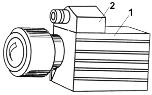
Fig. 3. External appearance of the AI NVG from the company
Video and Optical Systems Ltd. (UK) with TV image output:
1 – surveillance device, 2 – pulse laser illuminator.
NITECAM (Israel) developed TV AI NVG (model L 2001).
The device can operate with a line frequency of 625 or 525 Hz with a frame frequency of 25 and 30 Hz, respectively.
The device resolution is 350 TV lines.
Indicator – TV monitor with a screen size of 50 mm. Operating illumination 10-4 lux, operating spectral range 500 – 900 nm.
Observation device lens – Zoom with a focal length adjustable from 16 to 160 mm with a relative aperture of 1:1.8 with automatic adjustment of the iris diaphragm.
The angle of view is adjustable from 40 to 4°. The range in absolute darkness is 100 m.
Laser semiconductor illuminator (class 3v) with a radiation power of 10 mW, operating wavelength of 820 – 850 nm [1].
The safe distance for vision is 10 cm from the laser illuminator.
The device is powered by a voltage of 10 — 16 V at a direct current of 1.5 A.
Dimensions are 585x280x240 mm (excluding the battery, but including the viewfinder and optics) [1].
International Business Machines Corp. [1] has developed a TV AI NVG for aerial surveillance of ground objects (Fig. 4).
In order to consistently illuminate the observed terrain stripes, the ILPI (laser diode array) is made in the form of lines shifted in steps relative to each other.
The step of each step corresponds to the depth of the illuminated discrete section of the terrain.
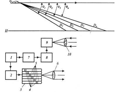
Fig. 4. Aircraft AI TV NVG from International Business Machines Corp.:
I – aircraft, II – terrain, j1 – jn – angles of inclination of the line of sight of the corresponding section of terrain in relation to the horizon line, D1 – D2 – distances to these sections, 1 – ZGI, 2 – pumping unit, 3 ILPI, 4 – ILPI laser diode lines, 5 light guides, 6 – radiation forming lens, 7 BRZ, 8 – FSI, 9 – TV camera with pulsed image intensifier, 10 its lens.
When using such NVDs, the optimal choice of a hybrid-modular converter (HMC) plays a decisive role, in which pulse control (strobing) is carried out mainly by the MCP of the image intensifier tube or by its photocathode.
For this purpose, Varo recommends the second-generation image intensifier tubes of model 5772, 9723, 9732 with a photocathode diameter of 18, 25 and 40 mm, respectively. For each model, the minimum strobe duration reaches 5, 20 and 50 ns, respectively [1].
The low-level television camera (LTV camera) from Fairchild (USA) [1] has a strobe duration of less than 1 ns. The strobe voltage is 200 V, the image intensifier tube conversion factor is 2×10⁴. The system resolution is 15 lines/mm, the dynamic range is 800. The number of elements of the CCD matrix is 512×512.
Kaman Sciences Corp. (USA) proposed a strobe GMF (ITT F4157 image intensifier (photocathode diameter 40 mm) + TN-7882 CCD (384×576 elements). The image intensifier tube is strobed by a grid shutter with a voltage of 150 V [1].
The Jai company (Denmark) offers TV AI NVG JAI 715 A and 716 G, strobed within the duration range of 0.1 – 16.7 µs. The horizontal resolution of the devices is 560 TV lines [1].
The Nanocam device from ?RDID (Israel) allows a strobe duration of less than 1 ns at a pulse frequency of 25 to 1000 Hz [1].
TV AI NVG SO477 from Hamamatsu (Japan) based on GMP for the spectrum range of 200 – 850 nm has a resolution of 450 TV lines, a field of view angle of 17° and operates with a strobe duration of less than 100 ns [1]. All image intensifier tubes of this company have strobe capability. The presence of two MCPs in the image intensifier tube allows increasing the brightness gain factor to 106 with a resolution of 32 lines/mm [1].
TV AI NVG from Stanford Computer Optics Inc. (USA) for the spectrum range of 130 – 920 nm operates at E = 5×10⁴-10-6 lux with a strobe duration of 5 ns [1].
Princeton Instruments Inc. (USA) has developed a GMP (generation II image intensifier + 512×512 element CCD matrix) with a dynamic range of 105, operating in the spectrum region of 0.18 – 0.9 µm with a strobe pulse duration of less than 5 ns [1].
Kodak (USA) offers a TV AI NVG based on a GMP (generation II image intensifier + one module of generation I image intensifier + CCD matrix). Resolution – 11 lines/mm. Dimensions 100x127x366 mm. Strobe duration changes in steps from 10 ns to 5 ms. The weight of the device is 4 kg [1].
Fairchild has developed a portable night vision device (NOD) for the UH-1 helicopter of the US Air Force. The device uses a laser semiconductor illuminator operating at a wavelength of 0.85 µm, emitting in an illumination angle of 9.5 x 30°. The receiving part is based on a GMP (an image intensifier with a photocathode diameter of 18 mm + a CCD of 575-575 elements). The strobe duration is 1 µs. The range of the device is 300 m [1].
The parameters of the portable night vision device Mark III Night Observation Device (NOD) by Mercury Engineering Inc. (USA) are presented in Table 1.
The PHS night vision device by RCA (USA) is of interest for controlling the landing and low-altitude flight of a heavy cargo helicopter [1].
The illuminator, based on a laser diode array, provides a spot of illumination on the ground with a constant diameter of 6 m at a helicopter flight altitude of 4.5 to 37 m. This is achieved using a lens with a smoothly variable focal length. The illumination frequency is 5 kHz, the illumination pulse duration is 50 ns.
The range and coordinates of the landing site are measured with an accuracy of ±1.2 m, which is achieved using an additional modulation frequency of 100 MHz.
Xedar Corp. (USA) has developed a whole series of TV AI NVGs designed for aerial searches for victims, collision avoidance with ships, and cargo delivery to unprepared airfields in any weather conditions. The main parameters of these devices are given in Table 1.
It was reported about the TV AI NVG [1], the image in which is output to a processing system that allows storing in memory up to four half-frames of the image in the television standard format 256x256x8 bits.
The illuminator is based on the LPI-103 semiconductor laser.
The receiving part of the NVD had an image intensifier with an MCP, coupled with a LI-702-3 supersilicon, which is part of the PTU-50 industrial installation. It was reported [1] about the possibility of using the AI TV for navigating hydrofoil vessels in adverse weather conditions.
In 1998, the State Unitary Enterprise SKV TNV NPO «Orion» created a portable observation TV AI NV «Berkut» (photo 7) to solve a wide range of national economic problems (exploration and extraction of minerals by underground and open-pit methods, construction work in difficult visibility conditions, etc.).
The NV «Berkut» (Table 1) has a built-in compact radio transmitter that provides remote transmission of a standard black-and-white TV signal in the decimeter wavelength range in any direction using a pin antenna.
When using a directional parabolic antenna with a diameter of 150 mm, the transmission range increases to 2.5 km, and using such an antenna with a diameter of 600 mm increases this range to 20 km, but in this case the NVD ceases to be portable.
The image is observed using a remote video monitoring device, the weight of which together with the receiving part of the radio transmitter, control panel and battery does not exceed 3.1 kg.
The primary power source for the NVD is a YUNLC-0.9 battery. The NVD weight together with the tripod in the working position does not exceed 20 kg [5].
Table 1. Main parameters of active-pulse NVDs (according to company prospectuses).
Literature
1. Geykhman I.L., Volkov V.G. Fundamentals of improving visibility in difficult conditions. Moscow, Nedra-Business Center, 1999, 286 p.
2. Volkov V.G. Application of active-pulse observation devices for seeing glare elements. Issues of Defense Technology, Series 11, 1995, Issues 1–2 (144–145), pp. p-7.
3. Mirage-1200. Device for detection of optical and optoelectronic systems and round-the-clock vision. Prospectus of NPC Transcript, Moscow, Russian Federation, 2001.
4. Golchenko A.N., Olikhov I.M. Semiconductor laser with electron pumping – a new short-pulse radiation source. Electronic industry, 1996, No. 3, pp. 65 – 70.
5. Volkov V.G., Koshchavtsev N.F., Leleikin V.I., Pleshkov A.A. Active-pulse portable television surveillance device with remote image transmission. Applied physics, 1999, issue 2, pp. 146-150.

Добавить комментарий